© Microhard Systems Inc. 23
3.0 Hardware Features
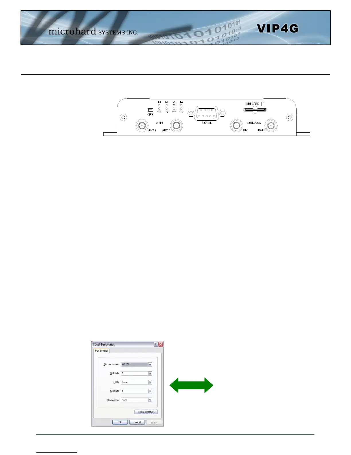
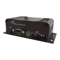
3.1.2.2 Rear
ANTENNA Connectors
The VIP4G uses female SMA antenna connectors for the Cellular and female RP-SMA connectors for the
WiFi antennas. Two antenna connections are provided for Wi-Fi, ANT1, and ANT2. Two connectors are
also provided for Cellular, MAIN and DIV.
Digital I/0 LED’s
The I-1, I-2, I-3, and I-4 LED’s indicate the status of the input pins on the digital I/O interface. The O-1, O-2,
O-3 and O-4 LED’s indicate the current state of the corresponding output relays.
Serial Port
The Serial port can be used for console type configuration (If disabled), or as a data communications port
for RS232 Devices.
CFG Button
Holding this button for 8 seconds while the VIP4G is powered up and running, will cause the unit to reset
and load factory default settings:
IP: 192.168.168.1 Subnet: 255.255.255.0
With these settings a web browser can be used to configure the unit.
Holding this button depressed while powering-up the VIP4G will boot the unit into FLASH FILE SYSTEM
RECOVERY mode. The default IP address for system recovery (only - not for normal access to the unit) is
static: 192.168.1.39.
Drawing 3-5: VIP4G Rear View
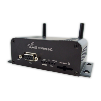
Default Console Port Settings:
Bits per Second: 115,200
Data Bits: 8
Parity: None
Stop bits: 1
Flow control: None