MSB780(X) - User’s Guide
Table 2: RS-232 default parameters
RS-232 default parameters
Baud Rate 9600
Data Bits 8
Parity None
Stop bits 1
Flow control none
Table 3: Connecting MSB780 or MSB780X to SDI-12
Connecting MSB780 or MSB780X to SDI-12
GND SDI-12 Ground Line
+ V Supply SDI-12 12 V Line
SDI-12 data line SDI-12 Data Line
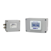
2.7 Connecting MSB780 or MSB780X to PC
To connect MSB780 or MSB780X to PC use serial cable (as described above). If the PC does
not feature a RS-232 port, a RS-232 to USB convertor may be used. After the sensor is con-
nected to PC, use a standard terminal program. Set serial line parameters according to section
“Serial Interface”. Each command is terminated by <cr>, or <cr><lf> ASCII characters. To test
the connection and settings, hit Enter. The sensor should reply as follows:
cmd??<cr><lf>
This reply means, that the sensor did not understand the command.
Note: By default, echo is turned off for MSB780 and MSB780X. If required, echo can be turned
on using echo1<cr> command.
2.8 SDI-12 interface wiring
To connect MSB780 or MSB780X to SDI-12 bus only 3 wires are needed, see table 3.
2.9 Service connector
Service connector enables connection to MSB780 at fixed communication parameters, see table
4. For serial service serial port the same commands as for user RS-232 are valid. Service con-
nector includes power supply connections (PWR+, GND), SDI-12 line and service UART (lines
SERVICE_RX, SERVICE_TX). Service UART is not directly compatible with RS-232. Service
UART uses 3.3 V voltage level. Direct connection to RS-232 may lead to damage of the barom-
eter. Special service cable with converter is required. This can be ordered from MicroStep-MIS.
15