158
- Console Port
The console port provides serial communication capabilities, which allows communication using RS-232 serial
port. The micro-USB port provides a direct connection to the switch and allows access to the CLI from a
console terminal connected to the port through the provided USB cable (with a male USB micro B connector
to male USB type A connector). The console port is separately configurable and can be run as an
asynchronous link from 1200 baud to 115,200 baud. The Dell EMC CLI supports changing only the speed of
the console port. The defaults are 115,200 baud, 8 data bits, no parity, 1 stop bit, and no flux control.
- USB Port
The Type-A, female USB port supports a USB 2.0-compliant flash memory drive. The Dell EMC Networking
N-Series switch can read or write to a flash drive with a single partition formatted as FAT-32. Use a USB flash
drive to copy switch configuration files and images between the USB flash drive and the switch. The USB flash
drive may be used to move and copy (for example for backup purpose) configuration files and images from
one switch to other switches in the network. The system does not support the deletion of files on USB flash
drives. The USB port does not support any other type of USB device.
- Port and System LEDs
The front panel contains light emitting diodes (LEDs) that indicate the status of port links, power supplies,
stacking, and the overall system status.
- Stack Master LED
When a switch within a stack is the master unit, the Stack Master LED is solid green. If the Stack Master LED
is off, the stack member is not the master unit. If a switch is not part of a stack (in other words, it is a stack of
one switch), the Stack Master LED is illuminated.
- Information Tag
The front panel includes a slide-out label panel that contains system information, such as the Service Tag,
MAC address, and so on.
- Thermal Shutdown
Upon reaching critical temperature, the switch will shut down for 5 minutes and then automatically power on
again. This cycle will repeat for as long as the switch is at or above critical temperature.
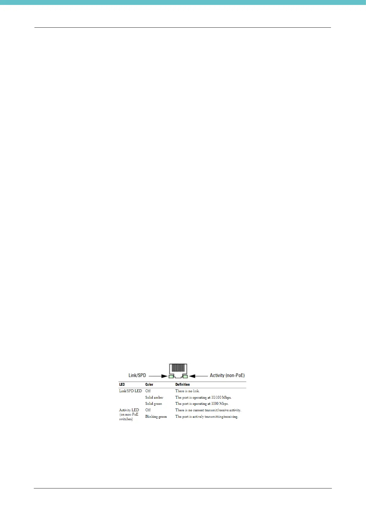
- Port LEDs
Each port includes two LEDs. One LED is on the left side of the port, and the second LED is on the right side
of the port. This section describes the LEDs on the switch ports. Each 100/1000/10000BASE-T port has two
LEDs. Figure 3-16 illustrates the 100/1000/10000BASE-T port LEDs.
- System LEDs
The system LEDs, located on the front panel, provide information about the power supplies, thermal conditions,
and diagnostics.