3 - 10 Operator’s Manual
3 System Preparation
3.7.2 Disconnecting a Probe
Perform the following procedure:
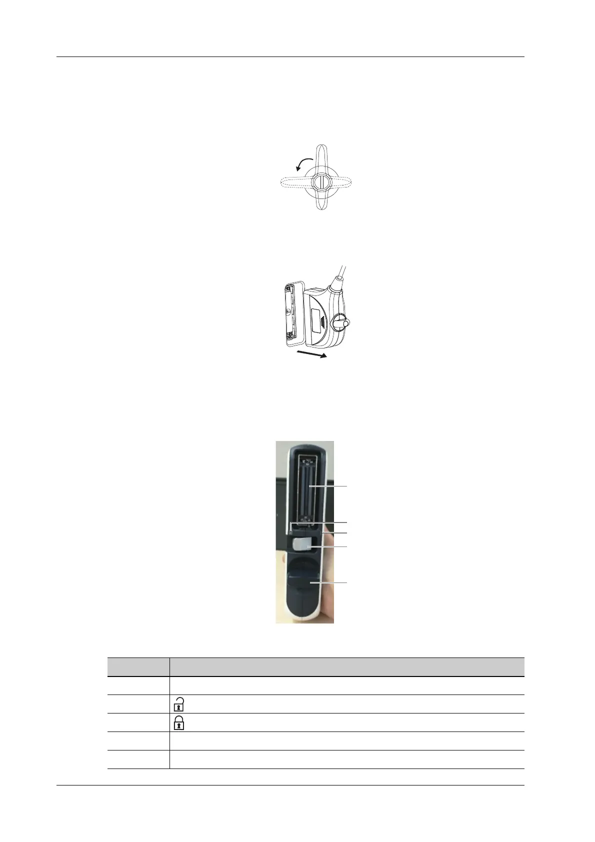
1. Turn the locking lever 90°counterclockwise to the horizontal position.
2. Pull the probe connector straight out vertically.
3.7.3 Installing a Probe Adapter
Figure 3-1 Probe Adapter Illustration
NO. Description
1. Probe socket
2. : Probe socket unlock position
3. : Probe socket lock position
4. Probe locking lever
5. Probe adapter locking lever
 Loading...


