. :
/>’
‘I,
SECTION
MITL91
OS/91
1
O-096-350-NA
Sheet 6 of 7
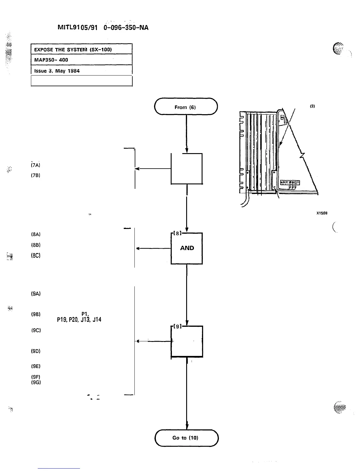
From (6)
7
._._
i7A)
..:
7”
(76)
-
t
AT FRONT OF EQUIPMENT
-171
(FIGURE 400-2)
Place equipment shelf and
power supply in position
f
AND
Secure equipment shelf with
eight 5-16 in. retaining screws
and washers
INSTALL
EQUIPMENT
(84
(86)
$3
(8C)
@D)
.
.
-
Place the maintenance panel in
position
Secure with four 5-16 in.
retaining screws and washers
Secure cable with a new cable
tie
If the system was
wall-mounted, release clip on
strikes and allow it to swing
down gently
Connect cables
PI,
P2, P3, P4,
P18,
P19,
P20,
513,
514
and
J15 (Figure 400-4)
Connect 5302 (optional), the
maintenance panel connector
and the OOT cable (Figure
400-3)
Plug power supply connector
into the back of the power
supply (Figure 400-4)
Secure power supply connectors
with four retaining screws
Connect cable ground lug
Secure power cable with new
cable ties
:.
?
Page D-8
SHELF
t
-El
AND
I
INSTALL
MAINTENANCE
INSTALL
MAINTENANCE
PANELPANEL
g
AND
CONNECT
CABLESCABLES
POWER SUPPLY
RETAINING SCREWS
(3)
\
.
CABLE SCREWS (4)
Figure 400-4
Power Supply Cable Harness
 Loading...