FX Series Programmable Controlers Applied Instructions 5
5-128
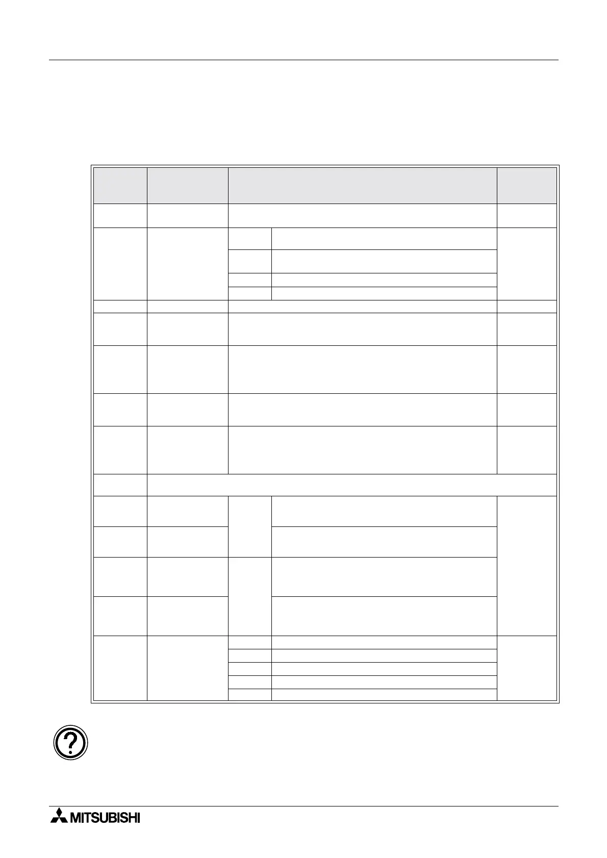
PID setup parameters; S3
The PID setup parameters are contained in a 25 register data stack. Some of these devices
require data input from the user, some are reserved for the internal operation and some return
output data from the PID operation.
Parameters S
3
+0 through S
3
+6 must be set by the user.
Parame-
ter
S3 + P
Parameter
name/function
Description
Setting
range
S
3
+0
Sampling time
T
S
The time interval set between the reading the current
Process Value of the system (PV
nf
)
1 to 32767
msec
S
3
+1
Action - reaction
direction and
alarm control
b0
Forward operation(0),
Reverse operation (1)
Not
applicable
b1
Process Value (PV
nf
) alarm enable, OFF(0)/
ON(1)
b2 Output Value (MV) alarm enable, OFF(0)/ON(1)
b3 - 15 Reserved
S
3
+2 Input filter α Alters the effect of the input filter. 0 to 99%
S
3
+3
Proportional
gain K
P
Thisisafactorusedtoaligntheproportionaloutputina
known magnitude to the change in the Process Value
(PV
nf
). This is the P part of the PID loop.
1to
32767%
S
3
+4
Integral time
constant T
I
This is the I part of the PID loop.
This is the time taken for the corrective integral value to
reach a magnitude equal to that applied by the
proportional or P part of the loop.
Selecting 0 (zero) for this parameter disables the I effect.
(0 to 32767)
x 100 msec
S
3
+5
Derivative
gain K
D
Thisisafactorusedtoalignthederivativeoutputina
known proportion to the change in the Process Value
(PV
nf
)
1 to 100%
S
3
+6
Derivative time
constant T
D
This is the D part of the PID loop.
This is the time taken for the corrective derivative value to
reach a magnitude equal to that applied by the
proportional or P part of the loop.
Selecting 0 (zero) for this parameter disables the D effect.
(0 to 32767)
x10msec
S
3
+7 to
S
3
+19
Reserved for use for the internal processing
S
3
+20
Process Value,
maximum
positive change
Active
when
S
3
+1,
b1 is
set ON.
This is a user defined maximum limit for the
Process Value (PV
nf). If the Process Value
(PV
nf) exceeds the limit, S
3
+24, bit b0 is set On.
0 to 32767
S
3
+21
Process Value,
minimum value
This is a user defined lower limit for the Process
Value. If the Process Value (PVnf) falls below the
limit, S
3
+24, bit b1 is set On.
S
3
+22
Output Value,
maximum
positive change
Active
when
S
3
+1,
b2 is
set ON.
This is a user defined maximum limit for the
quantity of positive change which can occur in
one PID scan. If the Output Value (MV) exceeds
this, S
3
+24, bit b2 is set On.
S
3
+23
Output Value,
maximum
negative change
This is a user defined maximum limit for the
quantity of negative change which can occur in
one PID scan. If the Output Value (MV) falls
below the lower limit, S
3
+24, bit b3 is set On.
S
3
+24
Alarm flags
(Read Only)
b0 High limit exceeded in Process Value (PV
nf)
Not
applicable
b1 Below low limit for the Process Value (PV
nf)
b2 Excessive positive change in Output Value (MV)
b3 Excessive negative change in Output Value (MV)
b4 - 15 Reserved
See Initial values for PID loops for basic guidance on initial PID values; page 5-114.
See page 10-24 for additional parameters available with FX
2N, FX2NC &FX1N MPUs.

 Loading...