FX Series Programmable Controlers Applied Instructions 5
5-201
5.16.1.1.6 Relationship between EXTR K10/K11 and A500/E500/S500 series
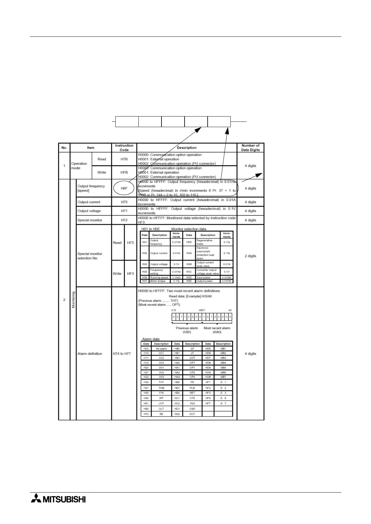
The page below is taken from section 4.2.41, paragraph 5 “Instructions for the program”
<setting items and set data> in the FR A500 series instruction manual, IB(NA)-66790-G
The following example reads the Output Frequency from Inverter station #1 and stores this
value to D100.
Number of digits, 2 or
4, is automatically
determined by the
PLC, based on the
instruction code.
EXTR K10 K1 H6F D100
 Loading...