FX Series Programmable Controllers Points Of Technique 10
10-16
The maximum output voltage (to the inverter) including ripple voltage, can be found by using
the following equation:
Where:
em = Maximum output voltage
E= pulse (square wave) output voltage (see circuit on the previous page)
t = PWM pulse duration (see previous page for reference)
T
0 = PWM cycle time for pulse (see previous page for reference)
The average output voltage (to the inverter) including ripple voltage, can be found by using the
following equation:
Where:
∆e = the voltage value of the ripple
e = ripple output voltage
T
0 = PWM cycle time for pulse
t = PWM pulse duration
τ = ripple circuit delay
See previous page for references.
Operation
Once the system configuration has been selected and the ripple circuit has been built to suit,
the motor speed may be varied by adjusting the value of 't' in the PWM instruction.
The larger the value of 't' the faster the motor speed will rotate. However, this should be
balanced with the knowledge that the faster the output signal changes the greater the ripple
voltage will be. On the other hand a slowly changing output signal will have a more controlled,
yet smaller ripple effect. The speed of the signal change is determined by the size of C1. A
large capacitive value for C1 would give a smaller ripple effect as charge is stored and
released over a longer time period.
The following characteristics were noticed when the identified circuit was tested
The PWM instruction had T
0 set to K50. The value for t was varied and also the load
impedance was varied to provide the following characteristics graph (see over page).
em ≈ E
t
T
0
T0 -t
τ
∆e
e
≈
T0
τ
≤
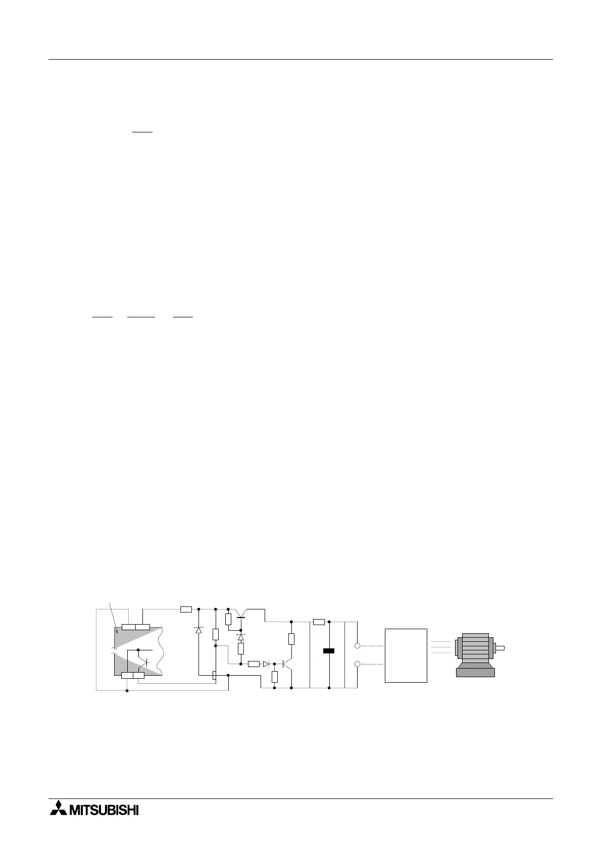
Y0
COM1
COM
24+
+
E
e
R1
R10
R7
R
4
R
5
R
6
R
9
R
8
Motor
Inverter
C1
5V
12V
Programmable
controller
Circuit configuration for a PLC with sink outputs.
The component values are the same as stated previously

 Loading...