170
(6) Input signal error detection signal (XC)
(a) Turning Input signal error detection signal (XC) ON
• Input signal error detection signal (XC) turns to ON when an analog input value exceeds the range set with
CH Input signal error detection setting value (Un\G142 to Un\G145) in any channel which has been A/D
conversion-enabled, after validating Input signal error detection setting (Un\G47).
• Input signal error detection signal (XC) turns to ON when an analog input value exceeds the range set with
CH Input signal error detection setting value (Un\G142 to Un\G145) in any channel which has been A/D
conversion-enabled, after setting the detection condition in Input signal error detection extension setting
(Un\G27). When the disconnection detection is set, the signal ignores the setting for CH Input signal error
detection setting value (Un\G142 to Un\G145), and turns to ON at the disconnection detection.
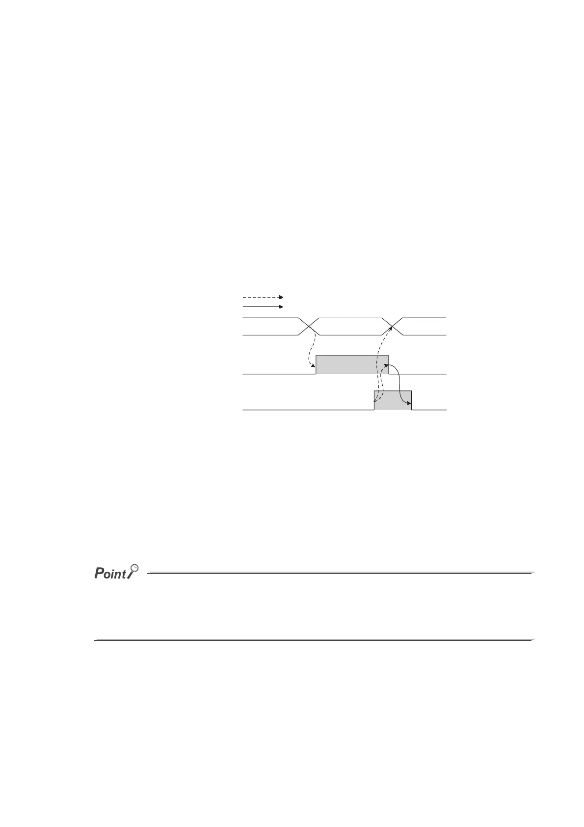
(b) Turning Input signal error detection signal (XC) OFF
After setting the analog input value within the range set, turn Error clear request (YF) OFF → ON → OFF to
turn OFF Input signal error detection signal (XC).
(c) When Input signal error detection signal (XC) turns ON
• A/D conversion completed flag (Un\G10) for the corresponding channels turns OFF.
• For the error detected channel, the digital output value immediately before the error detection is held in the
buffer memory.
• ALM LED flashes.
(d) When Input signal error detection signal (XC) turns OFF
• ALM LED turns off.
• Latest error code (Un\G19) is cleared.
When the analog input value falls within the range set, A/D conversion resumes regardless of Input signal error detection
signal (XC) reset.
When the first A/D conversion after the resumption is completed, A/D conversion completed flag (Un\G10) is turned to A/D
conversion completion (1).
Averaging processing starts over after the A/D conversion resumed.
0
Input signal error
detection
0
Input signal error detection
flag (Un\G49)
Input signal error detection
signal (XC)
Error clear request (YF)
Controlled by the A/D converter module
Controlled by the program
OFF
ON
OFF
ON
OFF
OFF
 Loading...

