3 - 82 3 - 82
MELSEC-Q
3 SPECIFICATIONS
3.5.44 Mode setting of Alert 1 to 4
(buffer memory address 192 to 195, 208 to 211: Un\G192 to Un\G195, Un\G208 to
Un\G211)
This setting is available in the setting mode only.
For confirming the change, it is necessary to turn on the setting change command
(YnB).
(1) Sets the alert mode which gives an alarm.
(2) The alert values of alert alarms 1 to 4 are set to the following buffer memory
addresses.
• Channel 1: 38 to 41
• Channel 2: 70 to 73
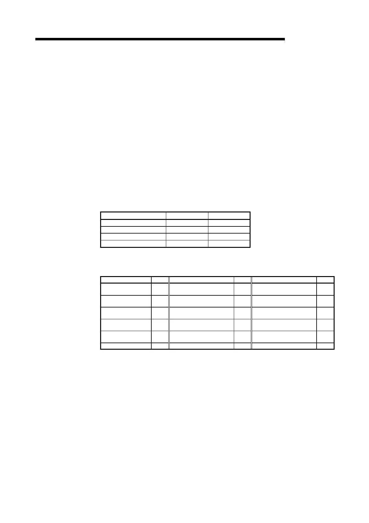
(3) The correspondences between buffer memory addresses and channels are
listed below.
Mode setting item CH1 CH2
Alert 1 192 208
Alert 2 193 209
Alert 3 194 210
Alert 4 195 211
(4) The following table indicates the alert modes and set values.
Refer to Section 3.2.10 for the alert functions of the Q62HLC.
Alert mode
Setting
Alert mode
Setting
Alert mode
Setting
Upper limit input alert 1
Upper limit input alert with
wait
7 — —
Lower limit input alert 2
Lower limit input alert with
wait
8 — —
Upper limit deviation
alert
3
Upper limit deviation alert
with wait
9
Upper limit deviation alert
with re-wait
12
Lower limit deviation
alert
4
Lower limit deviation alert
with wait
10
Lower limit deviation alert
with re-wait
13
Upper/lower limit
deviation alert
5
Upper/lower limit deviation
alert with wait
11
Upper/lower limit deviation
alert with re-wait
14
Within-range alert 6 — — — —
(5) The alert function is not executed with the default value "0"
3.5.45 Scaling value (buffer memory address 196, 212: Un\G196, Un\G212)
(1) The value which scaled the measured value (PV) is stored.
(2)
The scaling method differs depending on thermocouple input or micro
voltage/voltage/current input.
For details of the scaling function, refer to Section 3.2.14.

 Loading...


