EasyManua.ls Logo

Mitsubishi Q Series User Manual

Mitsubishi Q Series
244 pages
To Next Page IconTo Next Page
To Previous Page IconTo Previous Page
Page #91 background imageLoading...
Page #91 background image
3 - 60 3 - 60
MELSEC-Q
3 SPECIFICATIONS
3.5.2 Error code (buffer memory address 0: Un\G0)
Error code is stored when an error of Q62HLC occurs.
When checking the error code on the system monitor of GX Developer, monitor with
hexadecimal. The numeric value at the last digit shows the error code.
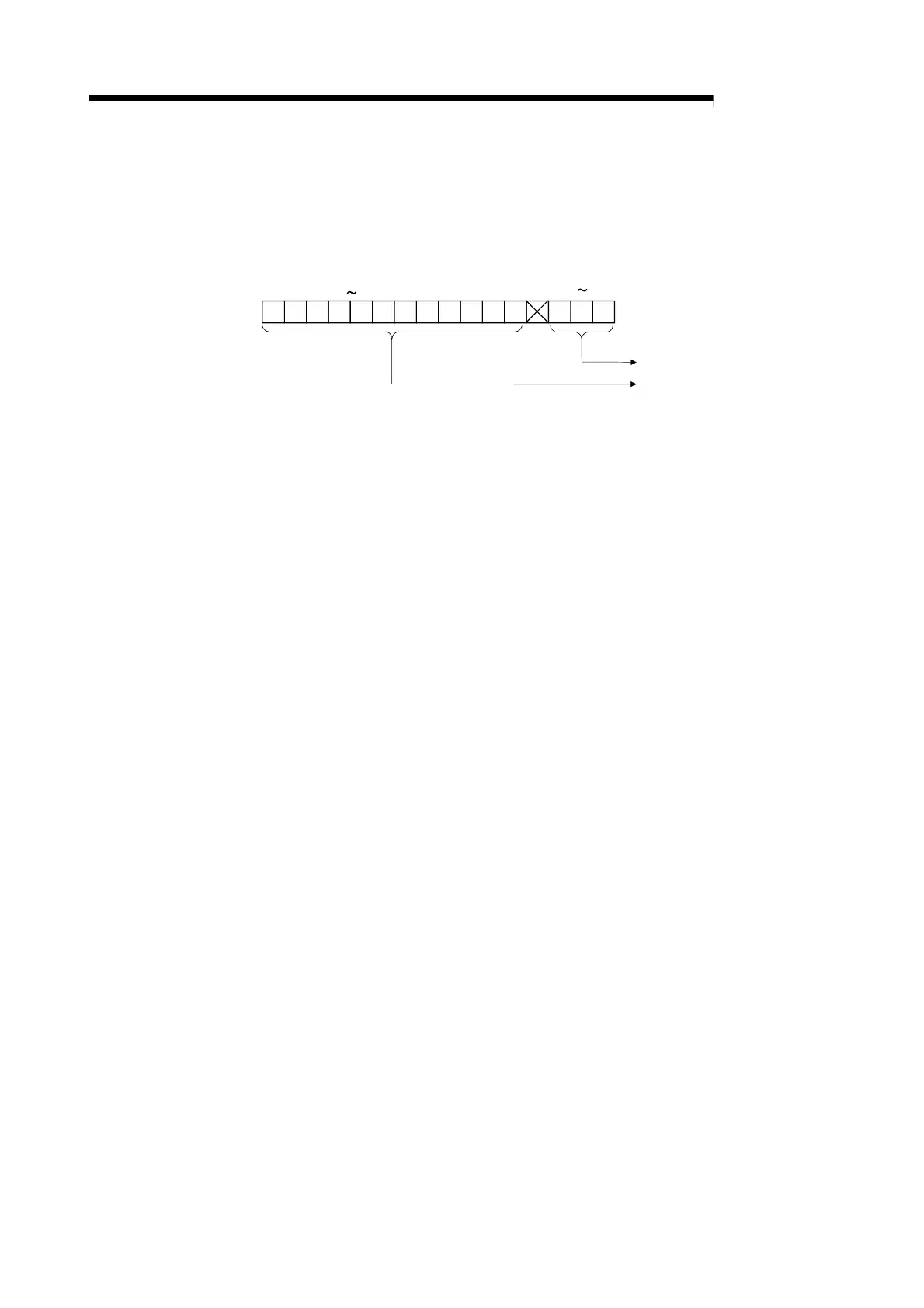
0
b15
b4 b2 b0
Error code
Error occurrence addres
s
(1) When data is written from the programmable controller CPU, the Q62HLC
checks:
Whether write data range is proper or not
(2) The following processings are performed at error occurrence.
• Error code is stored (refer to Section 8.1).
• The buffer memory address is stored in the error occurrence factor, when a
write data error occurs.
The factor code is stored in the error occurrence factor for AT error
completion or hardware error.
• Error flag (Xn2) is ON.
(3) If more than one error has occurred, the error code and error occurrence
address of the error having the highest priority are stored. (Refer to Section 8.1.)
(4) Refer to Section 8.1 for error resetting.

Table of Contents

Other manuals for Mitsubishi Q Series

Question and Answer IconNeed help?

Do you have a question about the Mitsubishi Q Series and is the answer not in the manual?

Mitsubishi Q Series Specifications

General IconGeneral
I/O PointsUp to 4096 points
CommunicationEthernet, RS-232, RS-485
I/O ModulesDigital, Analog, Specialized
Programming LanguageFunction Block Diagram, Structured Text
Power Supply24V DC, 100-240V AC
Operating Temperature0°C to 55°C
Shock Resistance147 m/s2 acceleration, 3 times in each of X, Y, and Z directions
Program CapacityUp to 252K steps

Summary

SAFETY PRECAUTIONS

Design, Installation, and Wiring Precautions

Covers safety guidelines for design, installation, and wiring to prevent hazards and malfunctions.

Startup, Maintenance, and Disposal Precautions

Safety measures for startup, maintenance, and proper disposal of the module.

SYSTEM CONFIGURATION

SPECIFICATIONS

Q62HLC Performance Specifications

Details analog I/O, input characteristics, accuracy, and conversion speed.

Auto Tuning Functionality

Explains the auto tuning function, execution procedure, and precautions.

PID Control Stop and Loop Disconnection Detection

Explains forced PID control stop and loop disconnection detection mechanisms.

Alert Function Details and Settings

Details various alert types (input, deviation) and their configuration.

Buffer Memory List and Error Codes

Comprehensive list of buffer memory addresses, settings, and detailed error codes.

Troubleshooting Common Issues

Guides for diagnosing issues based on LED indicators and specific error flags.

SETUP AND PROCEDURE BEFORE STARTING THE OPERATION

PROGRAMMING

ONLINE MODULE CHANGE

Online Module Change Procedure

Step-by-step guide for module change using GX Configurator-TC or sequence program.

Precautions for Online Module Change

Important safety and operational precautions to follow before and after module change.

TROUBLESHOOTING

Error Code List and Processing

Comprehensive list of error codes, their causes, and processing during errors.

Troubleshooting Common LED Indicators

Guides for diagnosing issues based on RUN, ERR, and ALM LED status.

Troubleshooting Specific Error Conditions

Addresses specific issues like auto tuning failures, module readiness, and alert flags.

Checking Q62HLC Status via GX Developer

Using GX Developer system monitor for status checks, error codes, and LED information.

Related product manuals