4 - 3 4 - 3
MELSEC-Q
4 SETUP AND PROCEDURE BEFORE STARTING THE OPERATION
4.3 Parts Identification
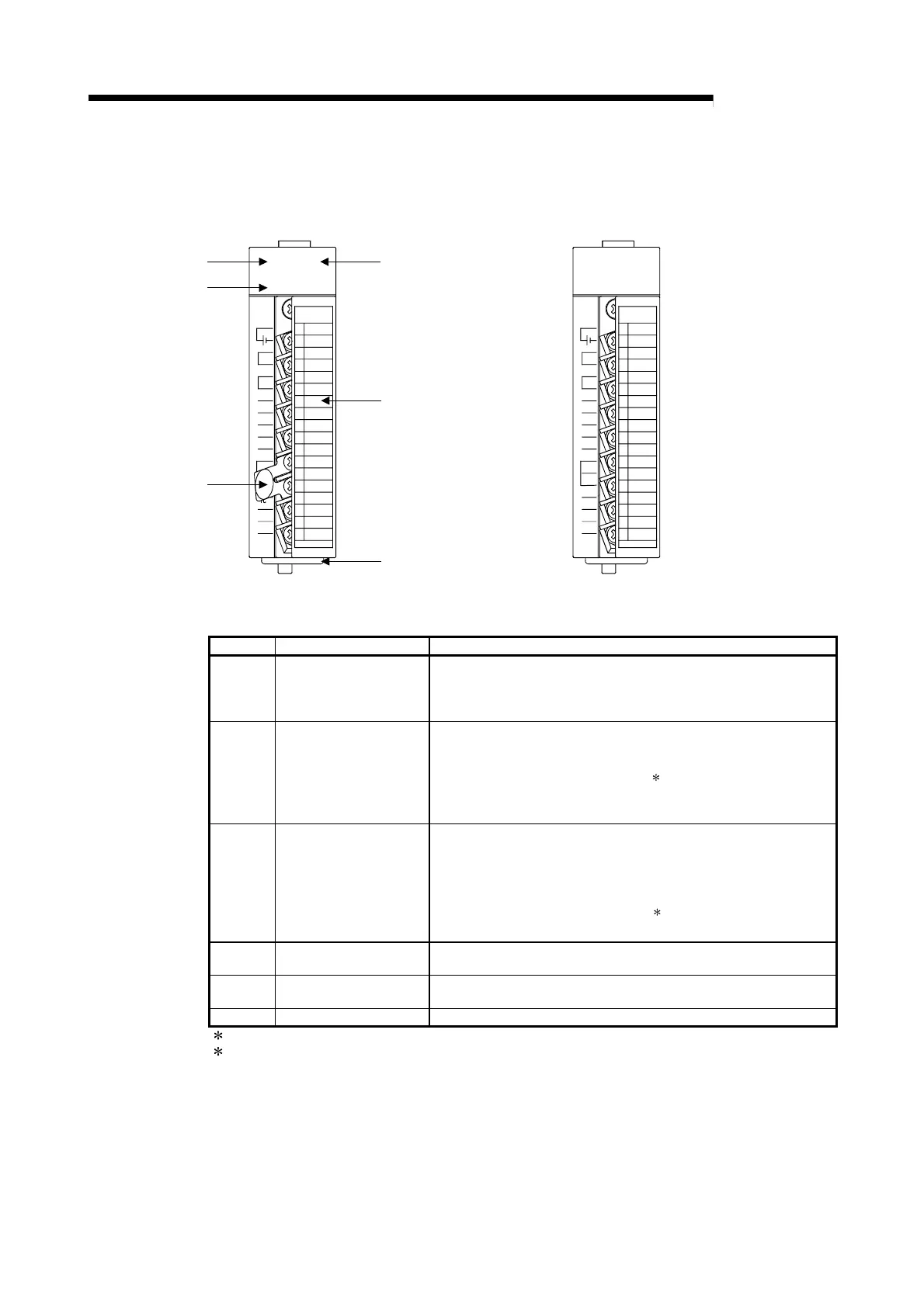
This section explains the names of the Q62HLC parts.
24VDC
IN
I+
I-
I+
I-
I+
mV+
Q62HLC
TC+/
V+
mV-
TC-/
CJ
+/
RUN
ERR.
ALM
mV+
TC-/
mV-
O
U
T
1
O
U
T
2
I
N
1
I
N
2
1
2
3
4
5
6
7
8
9
10
11
12
13
14
15
16
17
18
V-/I-
V-/I-
24VDC
IN
I+
I-
I+
I-
I+
mV+
Q62HLC
TC+/
V+
mV-
TC-/
CJ
TC+/
RUN
ERR.
ALM
mV+
TC-/
mV-
O
U
T
1
O
U
T
2
I
N
1
I
N
2
10
11
12
13
14
15
16
17
18
V-/I-
V-/I-
[Condition without temperature compensation resistor]
3)
4)
6)
1)
2)
5)
1
2
3
4
5
6
7
8
9
Number Name Description
1) RUN LED
Indicates the operating status of the Q62HLC.
On: Operating normally.
Off: 5V power is off, watchdog timer error occurred, or changing
online module is allowed.
2) ERR. LED
Indicates the error status of the Q62HLC.
On : Hardware fault (Includes the case of cold junction
temperature compensation resistance is not connected)
Flicker : Write data error occurring
1
When auto tuning is abnormally completed
Off : Operating normally.
3) ALM LED
Indicates the alert status of the Q62HLC.
On : Alert occurring
Flicker : Process value (PV) came out of measured temperature
range.
Loop disconnection was detected.
Sensor is not connected.
2
Off : Alert not occurring
4) Terminal block
Used for input to various sensors, current output, and external
power supply.
5)
Cold junction
compensation resistor
Used when cold junction compensation is made.
6) FG terminal Terminals for frame ground
1 : For details, check the error code. (Refer to Section 8.1)
2 : It may not be detected depending on the input range used. For details, refer to Section 3.1.2.

 Loading...


