3 - 49 3 - 49
MELSEC-Q
3 SPECIFICATIONS
3.5 Buffer Memory
3.5.1 Buffer memory list
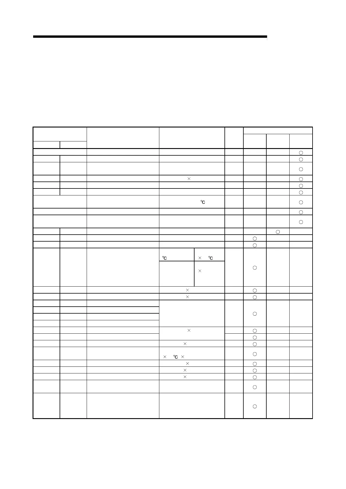
The following table shows the buffer memory list of the Q62HLC.
The area non-listed in the list is disabled. Do not write any data into the disabled
area.
Doing so may cause malfunction of programmable controller CPU.
Write condition *1 Address
(Decimal (Hexadecimal))
CH1 CH2
Settings Range
Default
value
Always
Setting
mode
Disabled
0(0H) Error code — 0 — —
5(5 H) 6(6 H) Alert definition — 0 — —
9(9 H) 10(AH) Measured value (PV) In accordance with input range
setting
— — —
13(D H) 14(EH) Manipulated value (MV) -50 to 1050 ( 0.1%) -50 — —
17(11H) 18(12H) Approach flag — 0 — —
25(19H) 26(1AH) Set value monitor — 0 — —
29(1DH) Cold junction temperature
measured value
-10 to 100 (
) — — —
30(1EH) Control mode monitor — 0 — —
31(1FH) FeRAMs PID constant read/write
completion flag
— 0 — —
32(20H) 64(40H) Input range 0 to 22 0 —
—
33(21H) 65(41H) Stop mode setting 0: Stop, 1: Monitor, 2: Warning 1
— —
34(22H) 66(42H) Set value (SV) setting Input range 0
— —
Thermocouples
(
)
1 to full-scale
( 0.1 )
35(23H) 67(43H) Proportional band (P) setting
Micro voltage
(mV), voltage
(V), current
input (mA)
1 to 10000
(
0.1%)
100
— —
36(24H) 68(44H) Integral time (I) setting 0 to 32767 ( 0.1s) 400
— —
37(25H) 69(45H) Derivative time (D) setting 0 to 32767 ( 0.1s) 100
— —
38(26H) 70(46H) Alert set value 1
39(27H) 71(47H) Alert set value 2
40(28H) 72(48H) Alert set value 3
41(29H) 73(49H) Alert set value 4
In accordance with alert mode
setting and input range setting
0
— —
42(2AH) 74(4AH) Upper output limiter setting 1050
— —
43(2BH) 75(4BH) Lower output limiter setting
-50 to 1050 (
0.1%)
-50
— —
44(2CH) 76(4CH) Output variation limiter setting 0 to 1000 ( 0.1%/s) 0
— —
45(2DH) 77(4DH) Sensor compensation value
setting
-5000 to 5000
(
0.1 , 0.01%)
0
— —
46(2EH) 78(4EH) AT differential gap 0 to 10000 ( 0.01s) 10
— —
47(2FH) 79(4FH) AT additional lag 0 to 1000 ( 0.01s) 10
— —
48(30H) 80(50H) Primary delay digital filter setting 0 to 1000 ( 0.1s) 0
— —
49(31H) 81(51H) Control response parameter
setting
0: Slow, 1: Normal, 2: Fast
0
— —
50(32H) 82(52H) Control mode 0: Normal control
1: Manual control 1
2: Program control
3: Manual control 2
0
— —
(To next page)
*1: Reading is always available regardless of the write conditions. The item of which write condition is set to
"Setting mode" is changeable on setting mode only. Note that changing items during the operation
mode causes a write data error. In addition, it is necessary to turn on the setting change command
(YnB) for changing the setting.

 Loading...


