3 - 41 3 - 41
MELSEC-Q
3 SPECIFICATIONS
3.4 I/O Signals Transferred to/from the Programmable Controller CPU
This section explains the allocation and applications of the Q62HLC I/O signals.
3.4.1 I/O signal list
(1) The Q62HLC uses 16 input points and 16 output points to transfer signals
to/from the Programmable Controller CPU.
(2) Table 3.7 lists the I/O signals used by the Q62HLC.
Inputs (X) mean the signals from the Q62HLC to the Programmable Controller
CPU and outputs (Y) the signals from the Programmable Controller CPU to the
Q62HLC.
(3) The I/O signals (X, Y) indicated in this manual assume that the module is loaded
on the I/O slot 0 of the main base unit.
If the Q62HLC is mounted on other than the I/O slot 0, change the I/O signals for
those of the slot where the module is mounted.
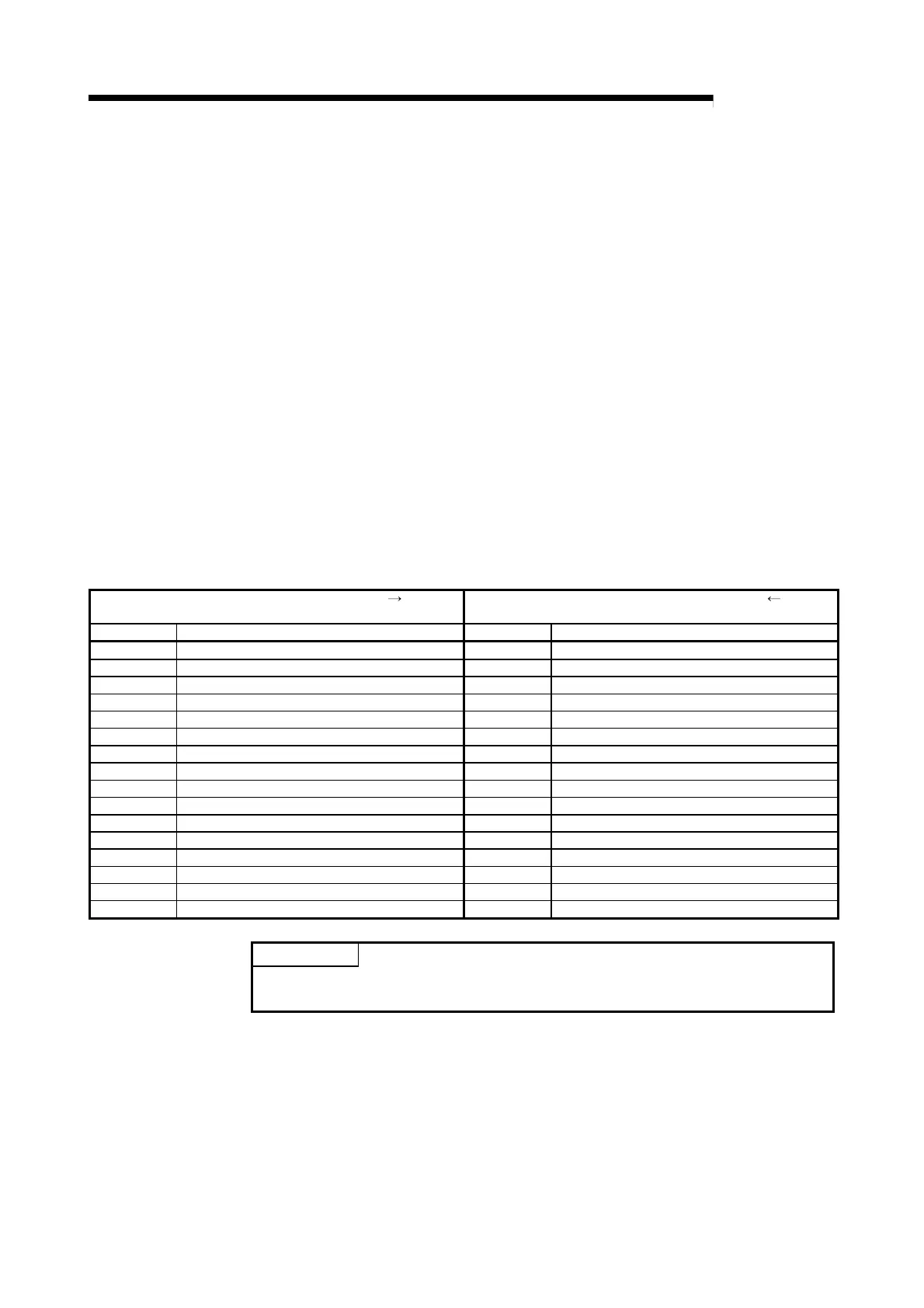
Table 3.7 I/O signal list
Input signal (Signal direction: Q62HLC
Programmable Controller CPU)
Output signal (Signal direction: Q62HLC
Programmable Controller CPU)
Device No. Signal name Device No. Signal name
Xn0 Watchdog timer error flag Yn0 Reserved
Xn1 Setting/operation mode status Yn1 Setting/operation mode command
Xn2 Error flag Yn2 Error reset command
Xn3 Module ready flag Yn3 Reserved
Xn4 CH1 auto tuning status flag Yn4 CH1 auto tuning command
Xn5 CH2 auto tuning status flag Yn5 CH2 auto tuning command
Xn6 Reserved Yn6 Reserved
Xn7 Reserved Yn7 Reserved
Xn8 FeRAM write completion flag Yn8 FeRAM backup command
Xn9 Default value write completion flag Yn9 Default setting registration command
XnA FeRAM write failure flag YnA Reserved
XnB Setting change completion flag YnB Setting change command
XnC CH1 alert occurrence flag YnC CH1 forced PID control stop command
XnD CH2 alert occurrence flag YnD CH2 forced PID control stop command
XnE Reserved YnE Reserved
XnF Reserved YnF Reserved
POINT
We cannot guarantee the functions of the Q62HLC if any of the reserved areas is
turned on/off in a sequence program.

 Loading...


