EasyManua.ls Logo

Mitsubishi Q Series User Manual

Mitsubishi Q Series
244 pages
To Next Page IconTo Next Page
To Previous Page IconTo Previous Page
Page #93 background imageLoading...
Page #93 background image
3 - 62 3 - 62
MELSEC-Q
3 SPECIFICATIONS
3.5.6 Approach flag (buffer memory address 17, 18: Un\G17, Un\G18)
(1) This flag checks if the measured value (PV) is within approach band.
(2) When the measured value (PV) is within approach band, the flag is "1".
Also, when the soak time (buffer memory address: 168) is set and the
measured value (PV) stays within approach band in the set time only, the flag is
"1".
3.5.7 Set value (SV value) monitor (buffer memory address 25, 26: Un\G25, Un\G26)
(1) The current value of set value monitor is stored.
The transitional change of set value during the program control is monitored
when setting the setting change rate limiter (buffer memory address: 52, 84).
3.5.8 Cold junction temperature measured value (buffer memory address 29: Un\G29)
(1) The measured temperature of cold junction temperature compensation resistor
mounted on Q62HLC is stored.
The value to be stored is in the range of –10 to 100 (-10 to 100
).
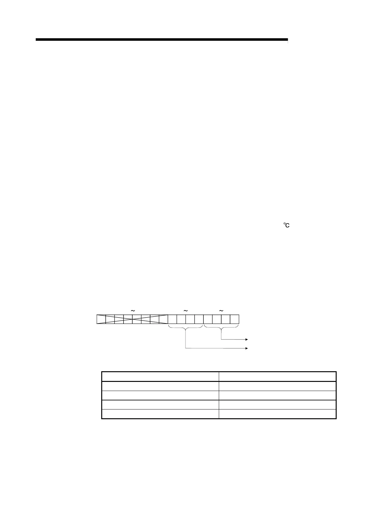
3.5.9 Control mode monitor (buffer memory address 30: Un\G30)
(1) When control mode, the switching value of control mode is stored after the
completion of shifting.
The value is configured with data of each channel 4 bits and stored in the lower
8 bits of buffer memory address 30.
The value of channel 1 is stored in 0 to 3 bits, and the value of channel 2 is
stored in 4 to 7 bits.
b15 b8 b3
CH1 value
CH2 value
b7 b4 b0
(2) The following describes the values to be stored.
Control mode Stored value
Normal control mode 0
Manual control mode 1
Program control mode 2
Manual control mode 3
(3) Set the manipulated value (MV) in manual control mode 1 and manual control
mode 2 after checking that the stored value is changed to 1 or 3.

Table of Contents

Other manuals for Mitsubishi Q Series

Question and Answer IconNeed help?

Do you have a question about the Mitsubishi Q Series and is the answer not in the manual?

Mitsubishi Q Series Specifications

General IconGeneral
I/O PointsUp to 4096 points
CommunicationEthernet, RS-232, RS-485
I/O ModulesDigital, Analog, Specialized
Programming LanguageFunction Block Diagram, Structured Text
Power Supply24V DC, 100-240V AC
Operating Temperature0°C to 55°C
Shock Resistance147 m/s2 acceleration, 3 times in each of X, Y, and Z directions
Program CapacityUp to 252K steps

Summary

SAFETY PRECAUTIONS

Design, Installation, and Wiring Precautions

Covers safety guidelines for design, installation, and wiring to prevent hazards and malfunctions.

Startup, Maintenance, and Disposal Precautions

Safety measures for startup, maintenance, and proper disposal of the module.

SYSTEM CONFIGURATION

SPECIFICATIONS

Q62HLC Performance Specifications

Details analog I/O, input characteristics, accuracy, and conversion speed.

Auto Tuning Functionality

Explains the auto tuning function, execution procedure, and precautions.

PID Control Stop and Loop Disconnection Detection

Explains forced PID control stop and loop disconnection detection mechanisms.

Alert Function Details and Settings

Details various alert types (input, deviation) and their configuration.

Buffer Memory List and Error Codes

Comprehensive list of buffer memory addresses, settings, and detailed error codes.

Troubleshooting Common Issues

Guides for diagnosing issues based on LED indicators and specific error flags.

SETUP AND PROCEDURE BEFORE STARTING THE OPERATION

PROGRAMMING

ONLINE MODULE CHANGE

Online Module Change Procedure

Step-by-step guide for module change using GX Configurator-TC or sequence program.

Precautions for Online Module Change

Important safety and operational precautions to follow before and after module change.

TROUBLESHOOTING

Error Code List and Processing

Comprehensive list of error codes, their causes, and processing during errors.

Troubleshooting Common LED Indicators

Guides for diagnosing issues based on RUN, ERR, and ALM LED status.

Troubleshooting Specific Error Conditions

Addresses specific issues like auto tuning failures, module readiness, and alert flags.

Checking Q62HLC Status via GX Developer

Using GX Developer system monitor for status checks, error codes, and LED information.

Related product manuals