3 - 90 3 - 90
MELSEC-Q
3 SPECIFICATIONS
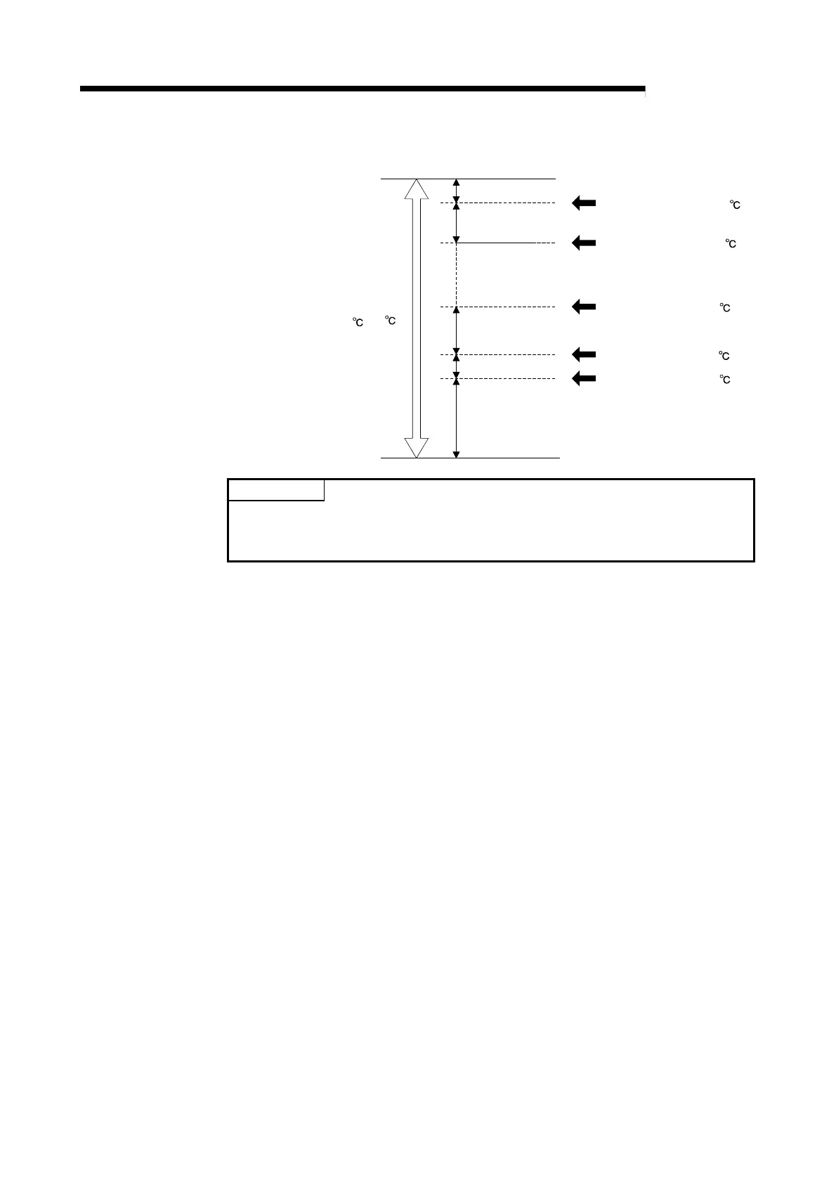
(Example) Thermocouple input
(1300 to 0 )
Zone 8
Zone 7
Zone 7 upper limit (1150 )
Zone 6 upper limit (1000 )
Zone 3 upper limit (700 )
Zone 2 upper limit (450 )
Zone 1 upper limit (350 )
Zone 3
Zone 2
Zone 1
Input range
POINT
When dividing a zone into four, set the upper limit for the zone 1 to 3 upper limit,
and set the upper limit (default value) of the input range for the zone 4 to 7 upper
limit.
(2) Zone 1 to 7 PID constant setting
(a) This setting sets the PID constants of proportional band (P), integral time (I)
and derivative time (D) corresponding to each zone set by the zone 1 to 8
upper limit.
(b) For details of the setting range, refer to Section 3.5.14.
(3) Zone 1 to 7 PID control response parameters
(a) This setting sets the control response parameters corresponding to each
zone set by the zone 1 to 8 upper limit.
(b) For details of the setting value, refer to Section 3.5.22.

 Loading...


