EasyManua.ls Logo

Mitsubishi Q Series User Manual

Mitsubishi Q Series
244 pages
To Next Page IconTo Next Page
To Previous Page IconTo Previous Page
Page #179 background imageLoading...
Page #179 background image
6 - 22 6 - 22
MELSEC-Q
6 PROGRAMMING
*2: Before executing program control, PID constants of zone1 and zone2 need to be set by the
program control auto tuning execution command (X111).
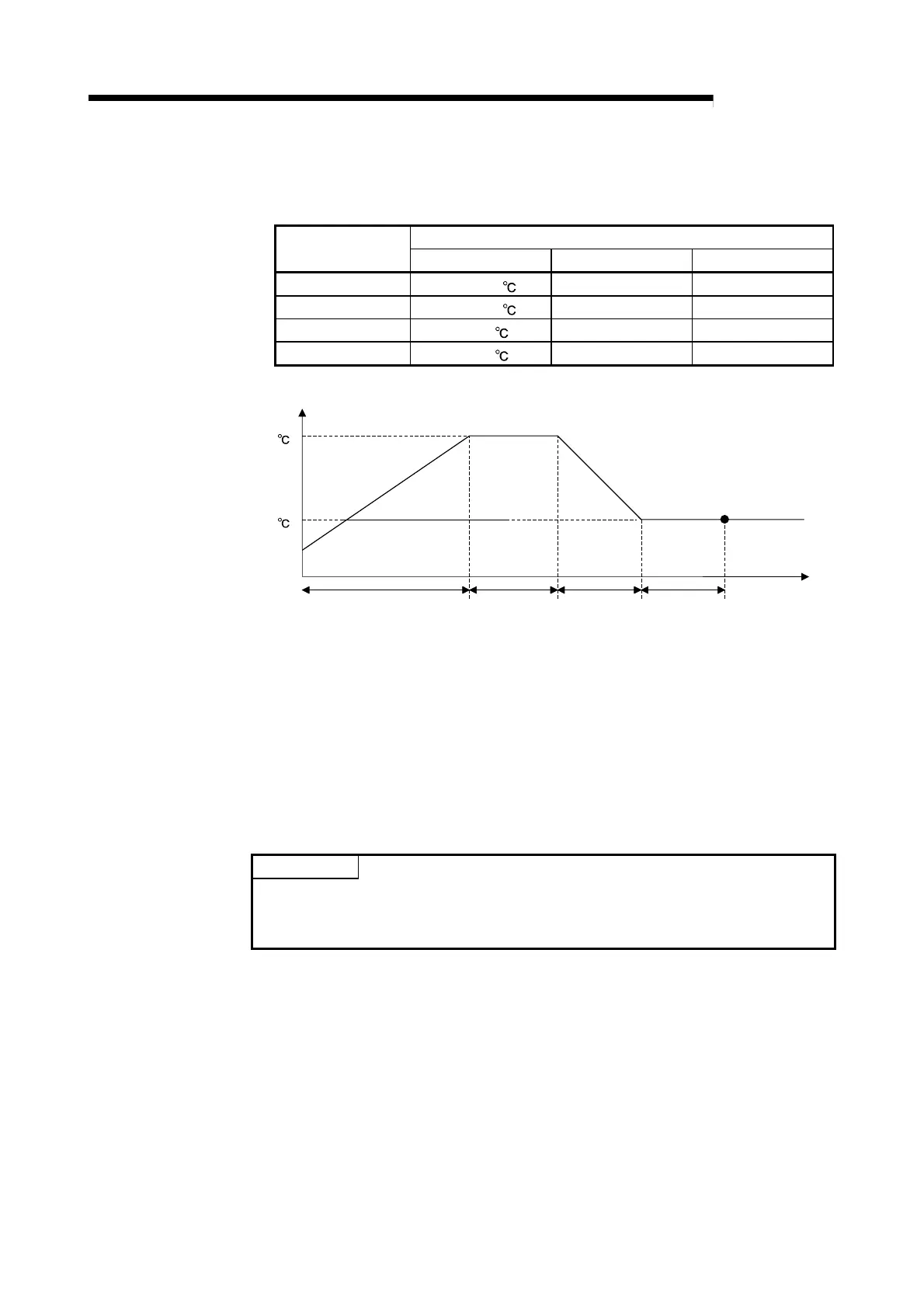
When program control is executed by the set pattern, it operates as follows.
Setting value
Segment number
Set value Executing time Zone PID data No.
Segment 1 1500 (150 ) 200 (200s) 2 (Zone 2)
Segment 2 1500 (150 ) 100 (100s) 2 (Zone 2)
Segment 3 500 (50 ) 100 (100s) 1 (Zone 1)
Segment 4 500 (50 ) 100 (200s) 1 (Zone 1)
Zone PID=2 Zone PID=2 Zone PID=1 Zone PID=1
Segment 1
200s
Segment 2
100s
Segment 3
100s
Segment 4
100s
Process Value (PV)
150
50
time
*3: After setting parameter by the cascade control setting command (X115), execute cascade
control by turning on the cascade control switching command (X108).
In this program example, the parameter setting for cascade control and the other parameter
settings (normal control, program control, and manual control2) cannot be set at the same
time.
After setting the parameter for cascade control, do not use the normal control mode switching
command (X104), program control mode switching command (X105), and manual control
mode 2 switching command (X107).
POINT
For details on the MELSECNET/H remote I/O network, refer to the Q
Corresponding MELSECNET/H Network System Reference Manual (Remote I/O
Network).

Table of Contents

Other manuals for Mitsubishi Q Series

Question and Answer IconNeed help?

Do you have a question about the Mitsubishi Q Series and is the answer not in the manual?

Mitsubishi Q Series Specifications

General IconGeneral
I/O PointsUp to 4096 points
CommunicationEthernet, RS-232, RS-485
I/O ModulesDigital, Analog, Specialized
Programming LanguageFunction Block Diagram, Structured Text
Power Supply24V DC, 100-240V AC
Operating Temperature0°C to 55°C
Shock Resistance147 m/s2 acceleration, 3 times in each of X, Y, and Z directions
Program CapacityUp to 252K steps

Summary

SAFETY PRECAUTIONS

Design, Installation, and Wiring Precautions

Covers safety guidelines for design, installation, and wiring to prevent hazards and malfunctions.

Startup, Maintenance, and Disposal Precautions

Safety measures for startup, maintenance, and proper disposal of the module.

SYSTEM CONFIGURATION

SPECIFICATIONS

Q62HLC Performance Specifications

Details analog I/O, input characteristics, accuracy, and conversion speed.

Auto Tuning Functionality

Explains the auto tuning function, execution procedure, and precautions.

PID Control Stop and Loop Disconnection Detection

Explains forced PID control stop and loop disconnection detection mechanisms.

Alert Function Details and Settings

Details various alert types (input, deviation) and their configuration.

Buffer Memory List and Error Codes

Comprehensive list of buffer memory addresses, settings, and detailed error codes.

Troubleshooting Common Issues

Guides for diagnosing issues based on LED indicators and specific error flags.

SETUP AND PROCEDURE BEFORE STARTING THE OPERATION

PROGRAMMING

ONLINE MODULE CHANGE

Online Module Change Procedure

Step-by-step guide for module change using GX Configurator-TC or sequence program.

Precautions for Online Module Change

Important safety and operational precautions to follow before and after module change.

TROUBLESHOOTING

Error Code List and Processing

Comprehensive list of error codes, their causes, and processing during errors.

Troubleshooting Common LED Indicators

Guides for diagnosing issues based on RUN, ERR, and ALM LED status.

Troubleshooting Specific Error Conditions

Addresses specific issues like auto tuning failures, module readiness, and alert flags.

Checking Q62HLC Status via GX Developer

Using GX Developer system monitor for status checks, error codes, and LED information.

Related product manuals