116
T26 System Manual Part 1: Installation
4.
Screw the two-wire cable to terminals 1 and 2: The cable does not necessarily need
to be attached to the terminal with the same number on both Info Module Mx2wire+
units. The device continues to function if connectors 1 and 2 are swapped.
Connectors 3 and 4 are only assigned if an external voltage source (48 V DC) is
used.
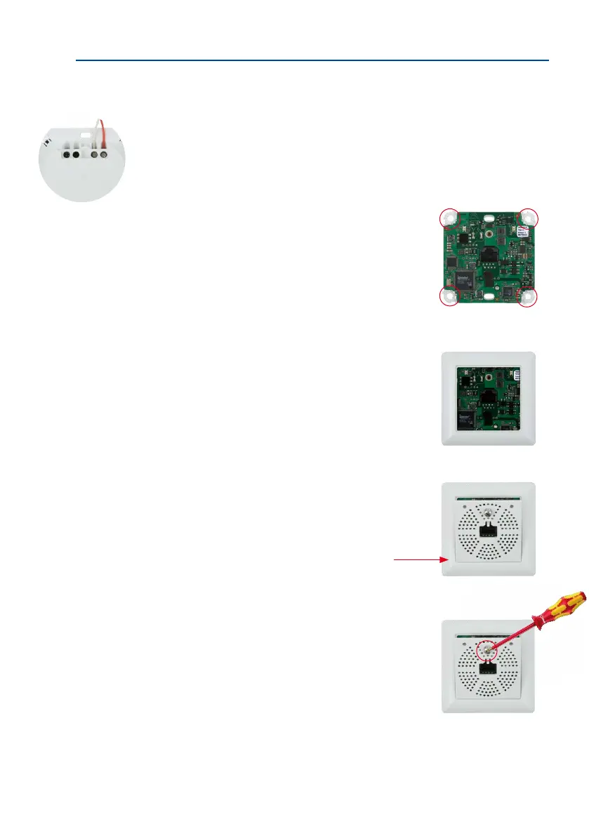
5. Insert the housing and circuit board into the sur
-
face-mounted socket: The two cable clamps on the
rear of the housing are located at the top. Attach the
housing and board to the surface-mounted socket by
fastening the four stainless steel screws in the four
existing drill holes.
6. Attach the frame: Place the selected frame (concave,
convex or at) onto the board and press down gently
until it automatically snaps into place. MOBOTIX is
printed on the bottom of the frame.
7.
Insert the panel: First insert bottom of front panel into
the frame as shown in the gure, then push against
top.
8. Screw the panel on tightly: Secure the front panel
using the panel’s stainless steel screw.
The device continues to
function if connectors
1 and 2 are swapped
Insert panel bottom rst, then
press the top into place