102
T26 System Manual Part 1: Installation
2.5.2 Connection Diagrams for Door Opener Versions
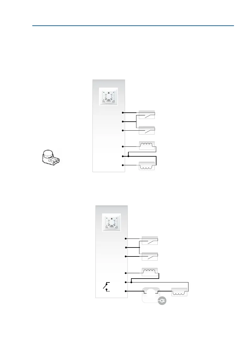
Version 1: Power Supply from MX-DoorMaster Battery (Self-Powered)
The MX-DoorMaster’s permanently-charged battery pack provides a supply voltage to the
door opener and therefore also bridges power failures.
Version 2: Power Supply from External Power Supply Unit (Internal Relay Function)
The MX-DoorMaster’s integrated relay function switches a maximum external voltage of 24 V
(SELV, max. 1 A).
Use the enclosed three-wire
connector for terminals that
are assigned two wires (IN –/
OUT –) (insert unstripped
wires and press down cutting
clamp with pliers)
Self-powered (stan-
dard version)
MX-DoorMaster
IN1 +
IN –
IN2 +
OUT1 +
OUT –
OUT2 +
Door sensor
Door lock sensor
The protection
Door opener
The MX-DoorMaster has an
integrated relay function
MX-DoorMaster
IN1 +
IN –
IN2 +
OUT1 +
OUT –
OUT2 +
Door sensor
Door lock sensor
Door opener
24 V AC
(SELV)
+ –
Power supply
The protection