Do you have a question about the Mobotix T26 and is the answer not in the manual?
Important notes and guidelines for product installation.
Requirements for electrical system installation and maintenance.
Protection measures against electrical surges and lightning.
Power consumption limits for connected MxBus modules.
Precautions for dark-colored modules in direct sunlight.
Safety instruction to disconnect power before camera access.
Configuration for network security and data protection.
Hemispheric camera records entire entrance area without blind spots.
IP video phone or computer connection for communication and door opening.
Camera records events automatically with sound.
Tamper-proof door opener control via RFID or PIN.
Digital voice messages for residents at the door station.
Door station connects via Ethernet or two-wire cabling.
180° fisheye lens for high-resolution overview images.
Automatic recording and notification upon movement detection.
Leaving voice messages and auto-playing audio messages.
Fisheye lens provides full scene overview, software corrects distortion.
Captures visitors from various angles, unlike standard 90° cameras.
High-resolution sensor for improved frame rate and image quality.
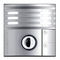
Allround view, internal memory, speaker, microphone.
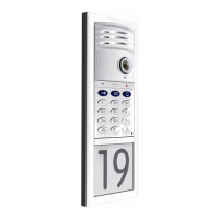
Keyless entry (RFID & PIN), video mailbox.
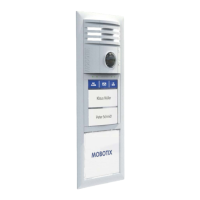
Interchangeable buttons, keyless entry (RFID), video mailbox.
Displays house number/name with backlighting.
Connects via two-wire cabling for data and power.
ETH Module and IO Module for connectivity and external devices.
T26-CamCore, KeypadRFID/BellRFID, Info Module, Info Module Mx2wire+.
Single, double, and triple frames with theft protection.
Housing for flush mounting, connected to subsurface or brickwork.
Controls door opener, provides backup power.
Communicates with outdoor unit, connects to network.
MxDisplay+, MxManagementCenter, MOBOTIX MxBell app.
NPA-PoE Set for power supply.
Modular system, compatible with future innovations.
Two-way video, sound, recording, light, doorbell.
Open/lock door, keyless access, voice mailbox.
Backlit for house number/name, optional Mx2wire+.
Data and power via two-wire, max 8 devices.
Mobile app for notifications, live views, and door operation.
Controls door, doorbell, LEDs, battery backup.
Remote unit for info module, two-wire connection.
Intercom, camera operation, door status monitoring.
Main external unit for the door station.
High-res camera with fisheye lens, speaker, microphone, storage.
Connects camera module via RJ45 to network cable without Mx2wire+.
Keyless entry with PIN/RFID, video mailbox.
RFID access, bell buttons, video mailbox.
Displays house number/name with permanent LED backlighting.
Connects via two-wire cable, requires indoor unit.
Robust, weatherproof housings and frames for module mounting.
Controls door opener, provides backup power, and acts as a doorbell.
Devices for remote interaction with the door station.
Wall-mounted intercom with WiFi, RFID, and touchscreen.
Mobile app for notifications, live views, and door operation.
Video management software for configuration and operation.
Additional components for the T26 system.
PoE adapter for network power supply.
Provides 8 signal inputs and 3 signal outputs for external devices.
Weatherproof network connector with surge protection.
High-precision time source and GPS event triggering.
Devices for providing power over Ethernet to the system.
Connects to any VoIP video phone for two-way communication.
Options for connecting door open/closed and lock sensors.
Connects to electrical door locking systems, tamper-proof.
Wiring diagrams for connecting the DoorStation.
Wiring diagram for connecting with the MX-DoorMaster.
Wiring for direct connection of door opener and sensors to access module.
Wiring for Mx2wire+ connection using bell wire and MX-DoorMaster.
Recommended cable types and maximum lengths for connections.
Guide for retrofitting an existing doorbell with a T26.
Connecting remote stations and network configuration.
Cable length limits and power supply requirements for Ethernet connection.
Connecting a single remote station using a PoE adapter.
Connecting multiple remote stations via PoE switch or adapter.
Connecting several T26 door stations to remote stations.
Instructions for mounting the door station frame and housing.
Deciding the optimal location and orientation for installation.
Guide for feeding cables through housing openings for on-wall and in-wall mounting.
Steps for securing the on-wall or cavity housing to the wall.
Routing cables correctly within the on-wall housing using cable binders.
Installing the Ethernet terminal board and connecting the network cable.
Instructions for correctly applying the gasket for weatherproofing.
Screwing the frame onto the housing and connecting the theft protection cable.
Activating and deactivating the mechanical theft protection lock.
Step-by-step guide for installing various T26 modules.
Installing the camera module via standard network connection.
Connecting camera module to Info Module Mx2wire+ via patch cable.
Inserting name plates and silicone insert for the BellRFID module.
Installing KeypadRFID or BellRFID modules, connecting cables.
Installing the info module and connecting cables for LED backlighting.
Installing Mx2wire+ info module and connecting the two-wire cable.
Personalizing the info module label using PDF templates.
Procedures for switching off theft protection and removing modules.
Installation instructions for the MX-DoorMaster.
Details of MX-DoorMaster connectors and functions.
Diagrams for self-powered and external power supply door opener versions.
Mounting the MX-DoorMaster in solid or cavity walls.
Steps for installing the MX-DoorMaster in wall sockets.
Installation guide for the Mx2wire+ indoor unit.
Description of Mx2wire+ technology and connection options.
Mounting options for the Mx2wire+ indoor unit.
Installing the Mx2wire+ indoor unit using a surface-mounted socket.
Explains the meaning of green and orange status LEDs.
Connecting external devices like lights, garage doors, or doorbells.
Connecting external devices using the IO Module.
Using access module outputs to control external devices like lamps.
Final steps for installation and system startup.
Verifying connections and activating theft protection.
Setting up signal output options for the MX-DoorMaster.
| Camera Resolution | 6MP |
|---|---|
| Weatherproof Rating | IP65 |
| Image Sensor | 1/1.8" CMOS |
| Max. Image Resolution | 3072 x 2048 |
| Power Supply | PoE (802.3af) |
| Operating Temperature | -30°C to +60°C |
| Microphone | Integrated |
| Speaker | Integrated |
| Interfaces | Ethernet |
| Protocols | SIP, RTSP |
| Audio | Full duplex |