126
T26 System Manual Part 1: Installation
2.8.2 Conguring the MX-DoorMaster
Before using the MX-DoorMaster, it is essential to congure the signal output option to be
used (see Section 2.5.2, «Connection Diagrams for Door Opener Versions»).
Three Options Are Available
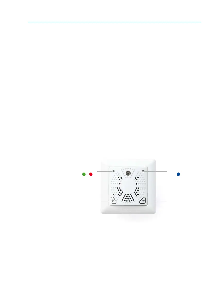
Option 1: Power Supply From MX-DoorMaster Battery (Self-Powered)
The door opener is supplied with a pulsed 12 V voltage (max. 10 W) from the battery. This
state is signaled by a green LED in conguration mode. As this is the factory default setting,
no further conguration is required for this connection option.
Option 2: Power Supply From External Power Supply Unit (Internal Relay Function)
The relay integrated into the MX-DoorMaster switches an external voltage that powers the
connected door opener. This is signaled by a red LED in conguration mode. Conguration
is required here (see below).
Option 3: Self-Locking Electronic Door Lock Including UPS Via Battery Pack
A DC control signal is switched to the control input of the electronic lock (special door opener
that keeps the door permanently locked). This is signaled by a blue LED in conguration
mode. Conguration is required here (see below).
Self-powered (stan-
dard version)
Internal relay function
Electronic lock (“Mediator”)
LED (blue)
Door opener
and emergency
unlocking (in the
event of a power
failure)
Doorbell
LED (green, red)