82
T26 System Manual Part 1: Installation
2.4 Installing the T26 Modules
Caution
Beware of short circuits: When you install the modules, the MxBus cable must not
be live. Make sure that the network cable is not connected to the PoE switch.
2.4.1 Installing the T26-CamCore Camera Module
Standard Network Connection
The Ethernet terminal board is used to connect the door station for the T26 version without
Mx2wire+ technology. It connects the short, pre-installed camera patch cable with the eight
split-out wires of the network installation cable (for installation, see Section 2.3.5, «Mounting
the Terminal Board and Fitting the Network Cable»).
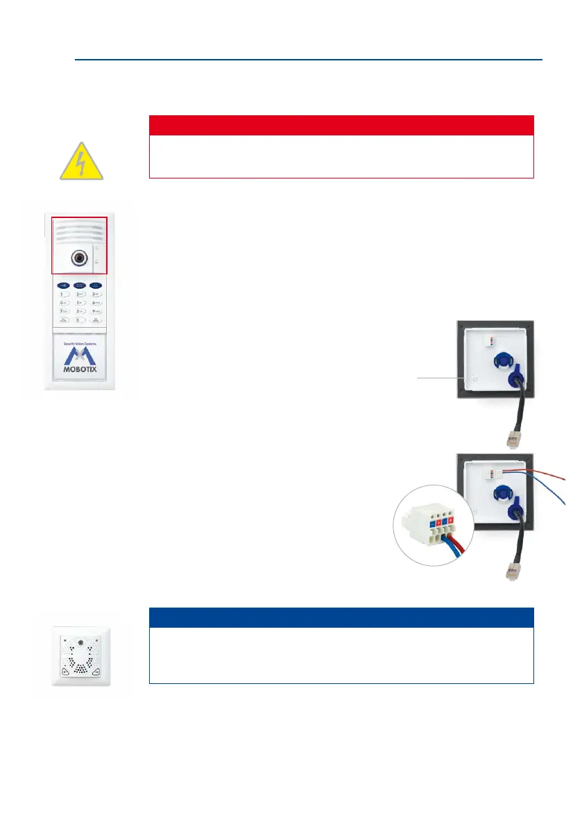
1. Ensure that the gasket is tted to the camera module.
2. Connect the supplied MxBus cable to the push termi
-
nal on the rear wall of the camera. Remove approx-
imately 5 mm of insulation from the cable ends
and push into the terminal.
• Red wire to + terminal
• Blue wire to – terminal
Note
To connect the MxBus cable of the MX-DoorMaster, the two free MxBus terminals
of the camera module can be used as an alternative to the MxBus terminals on the
access or info module (see Section 2.5, «Installing the MX-DoorMaster»).
Gasket
Do not swap the
+ and – wires
When using a dierent-col-
ored cable, make sure the
correct polarity is routed