113
Installing the Mx2wire+ Indoor Unit
2.6.3 Installation Using Cavity or In-Wall Socket
1. Prepare the cavity or in-wall socket: see Section 2.5.3
2.
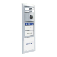
Screw the two-wire cable to terminals 1 and 2: The cable
does not necessarily need to be attached to the terminal
with the same number on both Info Module Mx2wire+
units. The device continues to function if connectors 1
and 2 are swapped.
Connectors 3 and 4 are only assigned if an external
voltage source (48-57 V DC) is used.
3.
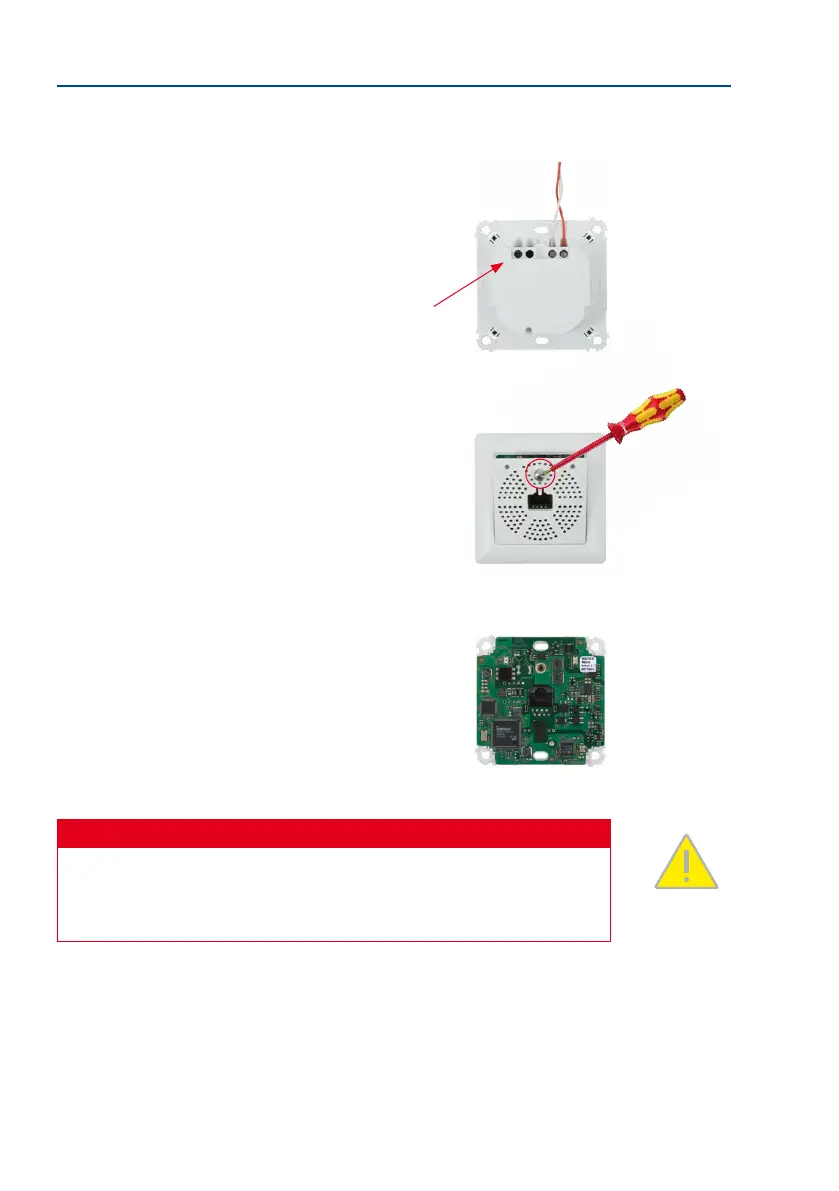
Remove the front panel and frame: In order to protect
the circuit board, the board is attached to the front
panel and frame in the original packaging. To continue
with the installation, however, you must rst separate
the housing and board from the panel and frame.
Loosen the screw in the front panel and li the panel
forwards.
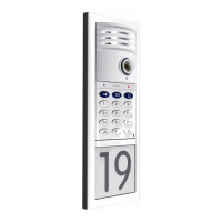
Now remove the attached frame from the circuit board.
Please note that you will need the stainless steel screw
in the front panel again later.
Safety Warning
Use this product in compliance with the applicable legal regulations. Electrical systems
and equipment may only be installed, modied and maintained by a qualied electrician
or under the direction and supervision of a qualied electrician in accordance with the
applicable electrical guidelines.
4 3 2 1
The screw does not need
to be removed completely
from the front panel