119
Connecting External Devices to the Door Station
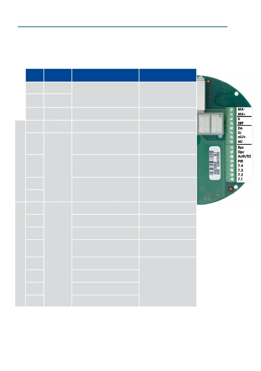
Terminal Connector Functions (External Devices and Third-Party System)
In addition to general technical specications for the signal inputs and outputs, the table
also shows the precise layout of the 16-wire terminal connector when the external devices
are modules from a third-party system.
Board
General
Function
Function of Third-Party System Comment
MX- MxBus-
MxBus
Direct connection to camera
module
MX+ MxBus+
b Gnd Ground Reference potential
3 signal outputs
ERT HW
Signal from eLi/c (half-wave rec-
tied)
Floor call when c ts eLi/c
Do
Max. switching voltage: 48 V AC, 48 V DC
Max. current: 2 A
Max. load: 60 W
Door opener
Relay switches b (door opener
still connected to c)
iLi Internal lights of third-party modules
Relay switches b (modules each
still connected to c)
eLi/c
Control for external light
(e.g., over the entrance door)
Isolated relay (NO type)
eLi
8 signal inputs
Bpc
Max. input voltage: 24 V AC, 24 V DC
Min. input voltage: 5 V AC, 5 V DC
Min. current: 2 mA
Door lock sensor (Bolt Position
Contact)
Contact switches c
Dpc Door sensor (Door Position Contact) Contact switches c
Auth/S2 Transponder/Fingerprint Module switches c
PIR PIR module/motion sensor Module switches c
7.4 Bell button 4
Bell switches c (full-wave) oor
call switches ERT (half-wave)
7.3 Bell button 3
7.2 Bell button 2
7.1 Bell button 1