59
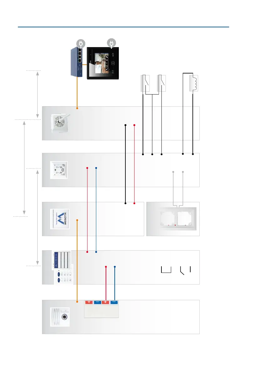
Overview: Connection and Wiring Diagrams
Modules are connected
via the looped-through,
two-wire MxBus cable that
transfers data and power
simultaneously (cable
included in packaging)
An Ethernet patch cable
is used to connect the
Mx2wire+ info mod-
ule to the camera
The module terminal des-
ignations are also located
directly on the module
The MX-DoorMaster is
always connected to a
free MxBus connector
of the outdoor station
(on the camera module,
access or info module)
T26-CamCore
MxETH
MX +
MX –
MX +
MX –
MX +
MX –
MX +
MX –
IN1 +
IN1 -
IN2 +
IN2 -
COM
COM
OUT A
OUT B
Door sensor
Door lock sensor
Door opener
e.g. PoE+ switch
Info Module Mx2wire+
The protection
(module frame
MxETH
48 V +
48 V –
Data A
Data B
max. 50 m/54.68 yd
Cable length depends on the two-wire cable used
(up to 500 m/546.81 yd)
MX-DoorMaster
MX +
MX –
IN1 +
IN –
IN2 +
OUT1 +
OUT –
OUT2 +
Mx2wire+
RJ45
48 V +
48 V –
Data A
Data B
max. 10 m/32.81
Connection of external devices (light relay,
etc.) and 12 V power supply unit
Patch cable
(usually short)
MxDisplay+
KeypadRFID/
BellRFID