June 15, 2005 6815854H01-A
4-30 Troubleshooting Procedures: Standard Bias Tables
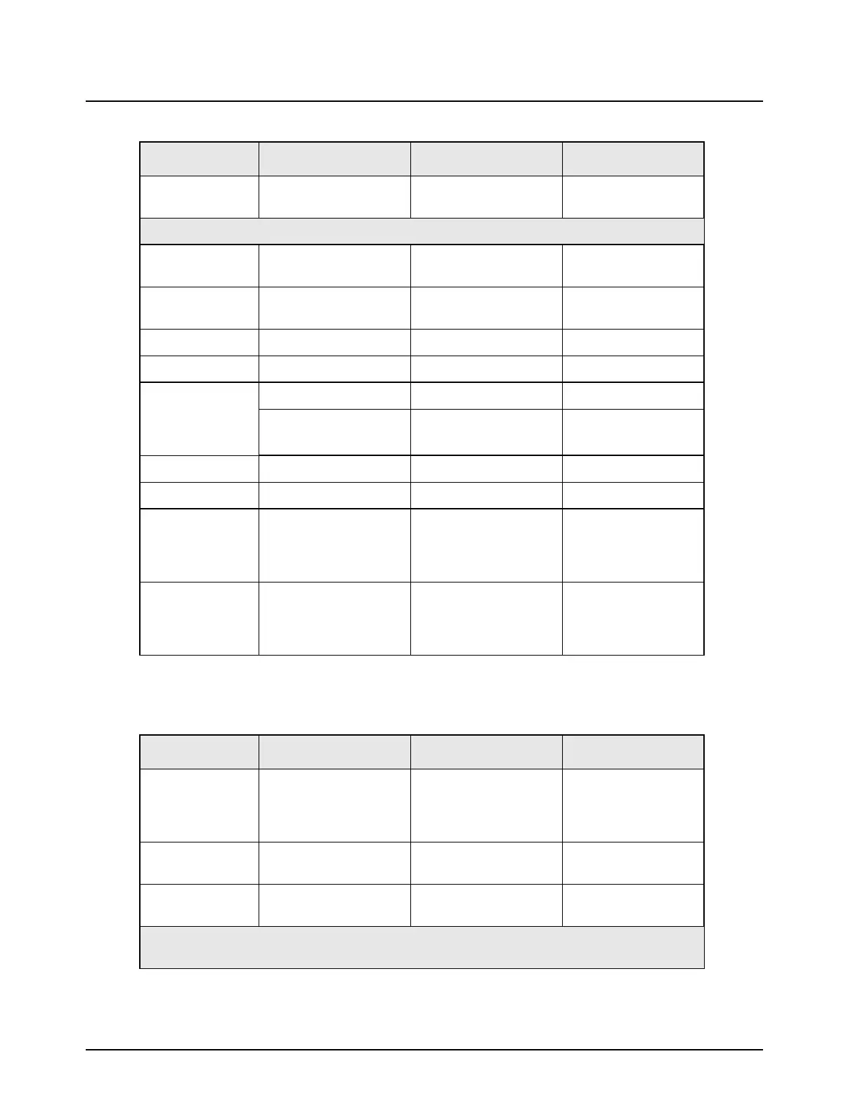
RS232__UARTA_RTS Flow control line—not
used always
TP0410, J2-10
Note: Use chassis as GND when measuring on an oscilloscope.
Approx. 0 V Emergency Idle = deactivated =
grounded
J2-15, J0402-28,
TP0403
1.88 V Emergency Activated = ungrounded J2-15, J0402-28,
TP0403
Approx. 0 V Emergency_sense Deactivated U508-4
2.85 V Emergency_sense Activated U508-4
(See “Chapter 6
Troubleshooting
Waveforms” on
page 6-1)
SAP_TX Idle = Radio ON J0401-35
SAP_RX Idle = Radio ON J0401-36
2.85 V SAP_DCLK Idle = Radio ON U0401-37
0 V SAP_FSYNC Idle = Radio ON U0401-38
(See “6.2.5
32 kHz Clock
Waveform” on
page 6-4)
32 kHz U0102-4
(See “6.2.4
16.8 MHz Clock
Waveform” on
page 6-3)
16.8 Mhz C0911 near U0903
Note: Do not KEY UP unless the board is inside a chassis.
Table 4-18. Standard Operating Bias: Audio Lines
Nominal Value Signal Name Range/State Probe Locations
9.2 V Mic_Hi When microphone
connected (expects
80 mV input) (line has
microphone bias)
TP0402, J0401-4
9.2 V Mic_Hi When microphone
disconnected
TP0402, J0401-4
13 V to 16 V Mic_Hi When programming
cable inserted
TP0402, J0401-4
Note: Do not press the PTT unless the PCB is inside a chassis even for a moment to check a line.
Permanent RF hardware damage can occur to the board due to no heatsinking.
Table 4-17. Standard Operating Bias: Clock and Control Lines (Continued)
Nominal Value Signal Name Range/State Probe Locations

 Loading...


