June 15, 2005 6815854H01-A
3-4 Theory of Operation: Power Management
3.4.1 Power Distribution
The control head houses 7 different power levels for smooth operation of the complex system of
XTL1500. They are A+ & SW_B+ at 13.8V (nominal battery terminal voltage), UNSW_VCC (3.0V),
SW_5V (5.0V), 1.55V, 1.88V, 2.8V and 3.3V.
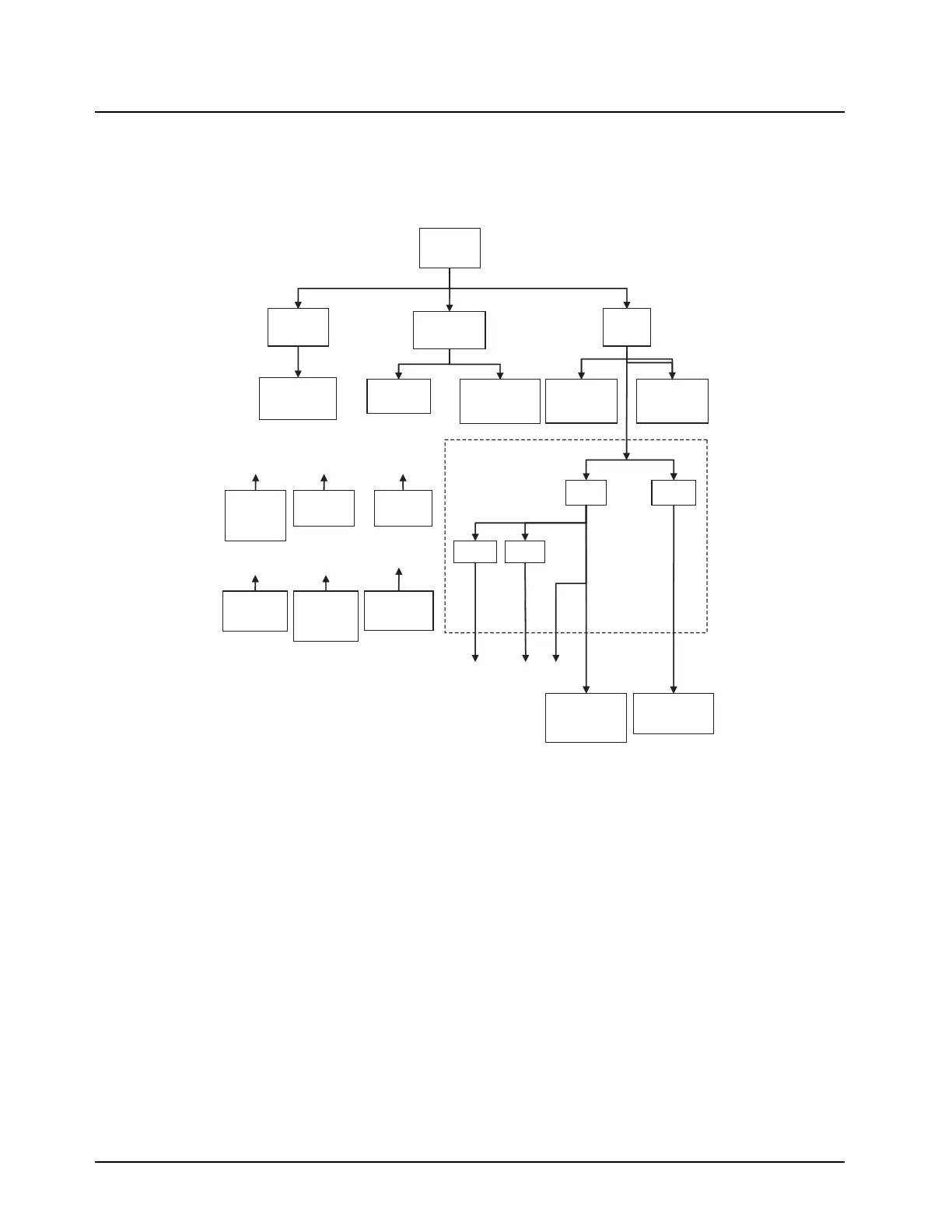
Figure 3-4. Control Head Power Distribution
The control head receives the main supply from A+ that comes from the brick, which is generally
about 13.8V (nominal battery terminal voltage). A+ is stepped down to UNSW_VCC through a low
power linear regulator IC (U2201). UNSW_VCC remains ON all the time even when the radio is in
the OFF state, mainly supplying to U2303 microcontroller and other logic gates that are essential to
the overall power control when the radio is OFF.
When the radio powers ON, A+ will be stepped down to 5V through the Switching Regulator IC
(U2200). Both USB host and TPS65012 Power Management IC (U2100) utilize the 5V supply.
U2100 is a specific IC made for OMAP IC, consisting of two switching regulators with hardware
selectable default output of 1.55V and 3.3V, and two linear regulators with default output voltage of
1.88V and one adjustable output configured to 2.8V. Input for the internal linear regulators is taken
from the 3.3V supply. Furthermore, U2100 also contains GPIOs that is controllable via I2C
communication with OMAP IC.
The 1.55V ensures smooth operation of OMAP’s ARM core. 3.3V supplies OMAP’s internal USB
module and its supporting circuitry. The 1.88V supplies the 8MB SDRAM (U1300) and OMAP’s
SDRAM associated data, address and control lines. 2.8V is the most widely used voltage in the
control head and it supplies to OMAP’s GPIOs, configuration resistors and all other parts of the
control head.
A+
13.8V DC
From Brick
Q2202
MOSFET
U2201
UNSW_VCC
SW_B+
(LEDs, Brick
Turn ON)
U2200
SW_5V
U2303
ATTiny13 C
U1001, U1003,
U1005, U1006
SSI Analog switch
U3100
USB Current
Limiter
U3101
USB/UART
MUX
1.88V 2.8V
1.55V 3.3V
U2100
TPS65012 Power
management IC
U1000
OMAP
ARM Core
Q2100
MOSFET
For Factory
Programming
U1000
OMAP
USB
U1301
FLASH
U1300
SDRAM
U1000
OMAP
GPIOs &
FLASH
U4202
ADC
Volume
control
1.88V
3.3V
2.8V 3.3V
2.8V 1.88V
U1000
OMAP
SDRAM
2.8V 2.8V 1.88V

 Loading...


