June 15, 2005 6815854H01-A
3-18 Theory of Operation: Receiver Front-End
3.10.1.5 Mixer (D3258)
The received signal is down-converted by a double-balanced mixer to an Intermediate Frequency
(IF) of 109.65 MHz. The mixer is designed to provide low conversion loss and high intermodulation
performance. The injection buffer provides a 20 dBm LO signal to the mixer. High-side injection is
used.
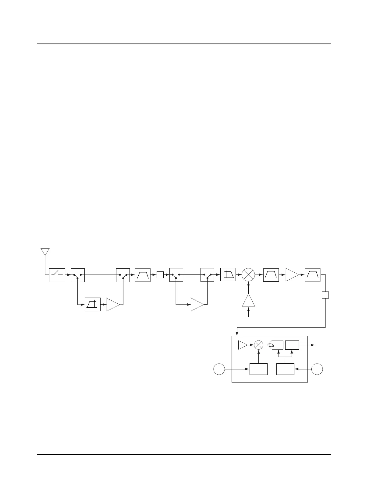
3.10.2 UHF Range 1 (380–470 MHz) Band
The receiver circuits primary duties are to detect, filter, amplify, and demodulate RF signals in the
presence of strong interfering noise and unintended signals. The receiver (see Figure 3-15) is
broken down into the following blocks:
• Front-end, which includes:
- High pass fIlter and first low-noise amplifier (LNA)
- Preselector filter
- Switchable 15 dB attenuator
- Second LNA
- Image Filter
- First mixer
• Back-end, which includes:
- Intermediate Frequency (IF)
- ABACUS III IC
Figure 3-15. Receiver Front-End and Back-End (UHF Range 1)
Ant. SW.
Harm. FLT
Pre-Amp
Switch
Pre-Amp
Switch
Pre-Amp
Switch
Pre-Amp
Switch
Mixer
Preselector
15 dB
Att.
Low Pass
Filter
RF Input
Crystal
24dBm
1st LO
Backend A/D Converter
SSI
Dec.
Filter
CLK
Synth.
LO
Synth.
2nd
LO
18MHz
CLK
IF Amp Crystal
109.65MHz
A
10 dB
Att.
380-470MHz
LNA
High Pass
Filter
LNA
ADC
ABACUS III IC
A

 Loading...


