SHOP MANUAL MT26/31 - 08.2006 SHOP MANUAL MT26/31 - 08.2006
SHOP MANUAL MT26/31 - 08.2006 SHOP MANUAL MT26/31 - 08.2006
TRANSMISSION
Ch 2 page 300 Ch 2 page 301
TRANSMISSION
TRANSMISSION
Ch 2 page 300 Ch 2 page 301
TRANSMISSION
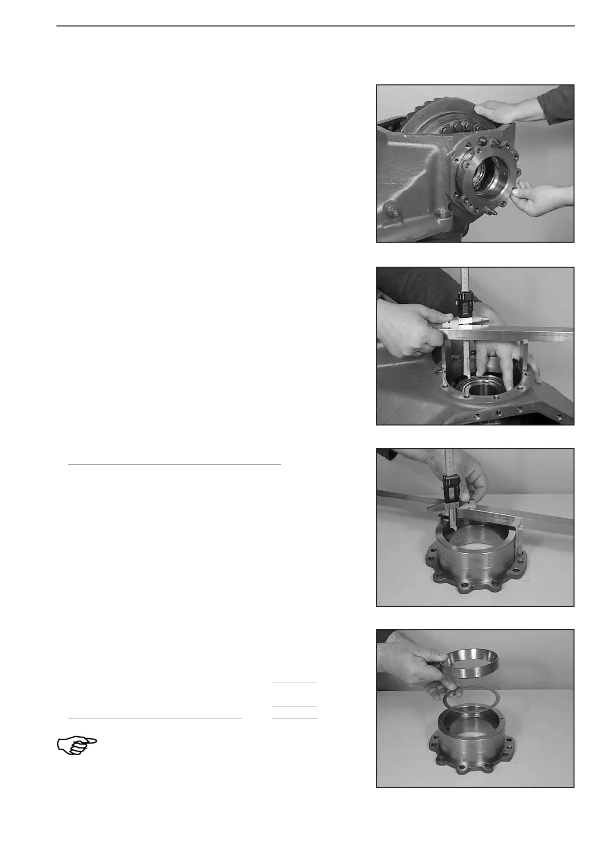
Figure 611
Figure 614
Figure 613
Figure 612
Install two adjusting screws.
Introduce bearing cover I and fasten it provisionally with four
screws.
Torque limit .............................................. 79 Nm
(S) Adjusting screws 504186
EXAMPLE “R“:
Dimension I e.g. ................................. 41,60 mm
Dimension II e.g. ................................
− 39,90 mm
Difference ........................................... = 1,70 mm
Required bearing preload e..g. + 0,30 mm
Gives Shim s = 2,00 mm
Bearing preload = 0,3 ... 0,4 mm corresponds
with the required bearing rolling moment
T = 3 ... 4 Nm !
Install shim e.g. 2,00 mm and bearing outer race.
Bearing cover II (opposite the crown wheel side):
Measure Dimension II from the mounting face to the locating face
bearing outer race.
Dimension II e.g. ...................................... 39,90 mm
Tilt axle drive housing 90°.
Mount bearing outer race, press it uniformly on and determine
Dimension I from the mounting face to the bearing outer race.
Dimension I e.g. ................................... 41,60 mm
(S) Straightedge 504170
(S) Gauge blocks 504173
(S) Digital Depth gauge 504175