SHOP MANUAL MT26/31 - 08.2006 SHOP MANUAL MT26/31 - 08.2006
SHOP MANUAL MT26/31 - 08.2006 SHOP MANUAL MT26/31 - 08.2006
TRANSMISSION
Ch 2 page 304 Ch 2 page 305
TRANSMISSION
TRANSMISSION
Ch 2 page 304 Ch 2 page 305
TRANSMISSION
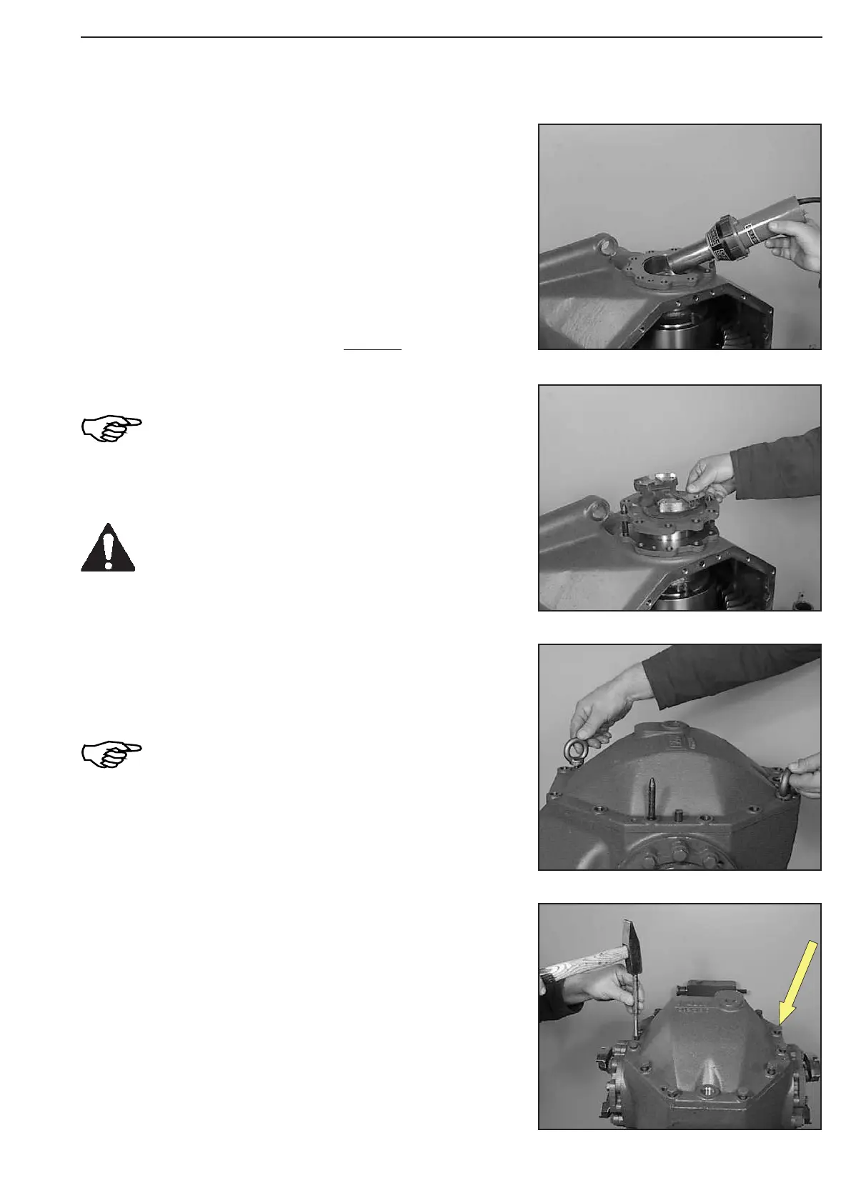
Figure 624
Figure 627
Figure 626
Figure 625
Heat bearing bore (about 90° C).
(S) Hot-air blower 230 V 504193
(S) Hot-air blower 115 V 504194
Locate cover by means of hex. head screws (do not tighten) and
drive the two roll pins flush-mounted in.
Now, tighten the cover finally, using hex. head screws.
Torque limit (M12/10.9) .......................... 115 Nm
Wet mounting face with sealing compound Loctite
(Type-No. 574).
Install two adjusting screws and position cover against shoulder.
Pay attention to the radial installation location !
(S) Adjusting screws 504186
Introduce the flange shaft and fasten it uniformly by means of hex.
head screws.
Torque limit (M12/8.8) ................................. 79 Nm
LH and RH seal retainer are different !
Pay attention to the installation position and
the radial installation location, see the
markings, applied at the disas-sembly !
Now, install opposite flange shaft accordingly (Fig. 620 ... 625).
After the assembly of the two seal retainers,
relax the differential bearing by tapping (use
plastic mallet) !
(S) Plastic mallet 504196