N715-EA Hardware User Guide
Chapter 5 Application Interfaces
Copyright © Neoway Technology Co., Ltd. All rights reserved.
⚫
Select an enhanced p-MOSFET at Q1, of which the safe operating voltage is at least 12 V
(V
dss
=-12 V) and drain current is at least 3.5 A (I
D(MAX)
=-3.5 A) and Rds is low (R
ds(on)
=108 mΩ).
⚫
Select a common NPN tripolar transistor at Q2. Reserve enough tolerances of R1 and R2 in
design, especially for the situation in which operating voltage of the tripolar transistor might
increase in low temperature; it is recommended that the value of R2 be at least 10 times that of
R1.
⚫
Keep the placement of C3 close to the module. A large tantalum electrolytic capacitor (220 μF or
100 μF) or aluminum electrolytic capacitor (470 μF or 1000 μF) can be selected at C3 to improve
the instantaneous large current freewheeling ability of the power supply. Its withstand voltage
should be larger than 2 times the voltage of the power supply.
⚫
Place the bypass capacitors (C4, C5, C6, C7) of low-ESR close to the module to filter out high-
frequency jamming from the power supply.
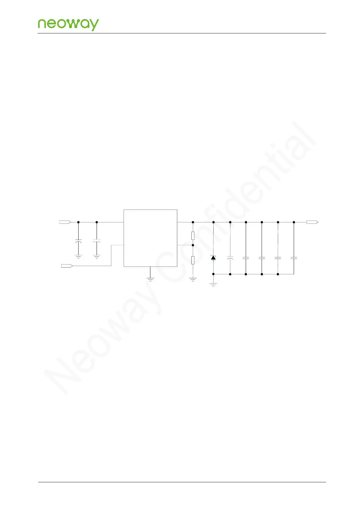
Recommended 4.2 V to 5.5 V input design:
Figure 5-4 Recommended design 3
VIN
TVS
D3
C3
100uF
C4
10uF
C5
0.1uF
C6
100pF
C7
33pF
VBAT
EN
GND
VOUT
ADJ
PWR_EN
C1
100uF
C2
0.1uF
R1
R2
U1
VIN
100kΩ
47.5kΩ
⚫
Design with LDO is simpler and more efficient when the system power input is close to the
permissible voltage across VBAT.
⚫
Select an LDO that can output 3 A current at U1 to ensure the performance of the module.
⚫
In order to protect the back-end components and the module, place the TVS diode close to the
power input interface to suppress the surge voltage before it enters back-end circuits
⚫
Keep the placement of C3 close to the module. A large tantalum electrolytic capacitor (220 μF or
100 μF) or aluminum electrolytic capacitor (470 μF or 1000 μF) can be selected at C3 to improve
the instantaneous large current freewheeling ability of the power supply. Its withstand voltage
should be larger than 2 times the voltage of the power supply.
⚫
Keep the placement of the bypass capacitors (C4, C5, C6, C7) of low-ESR close to the module
to filter out high-frequency jamming from the power supply.
Recommended 5.5 V to 24 V input design: