N715-EA Hardware User Guide
Chapter 5 Application Interfaces
Copyright © Neoway Technology Co., Ltd. All rights reserved.
communications
FW in open version: used
for data transmission.
Used for data transmission
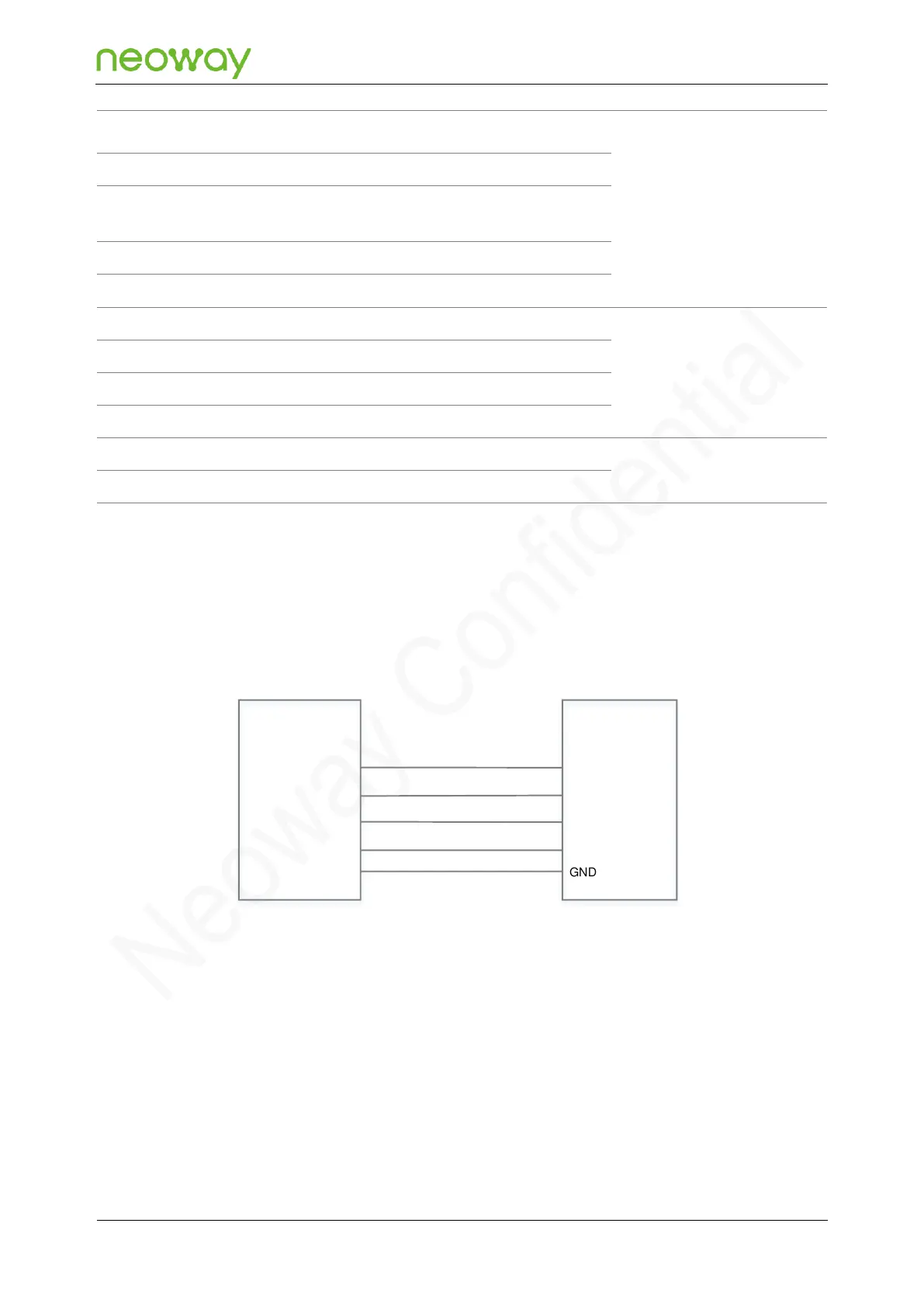
N715-EA provides three UART interfaces, two of which support hardware flow control. They support
1.8 V level and baud rates up to 921600 bps. The following figure shows recommended design of
UART interface.
Figure 5-15 Reference design of UART interface
N715-EA Module
UART_RXD
UART_TXD
UART_CTS
UART_RTS
GND
Device
MCU_TXD
MCU_RXD
MCU_UART_RTS
MCU_UART_CTS
GND
Schematic Design Guidelines
⚫
Pay attention to the corresponding relations between the signal direction and the connection.
⚫
It is prohibited to use diodes for voltage-level translation.
If the UART does not match the logic voltage of the MCU, add a voltage-level translation circuit outside
of the module. Three transistor translation circuits are recommended based on the differences in logic
levels and rates.