N715-EA Hardware User Guide
Chapter 5 Application Interfaces
Copyright © Neoway Technology Co., Ltd. All rights reserved.
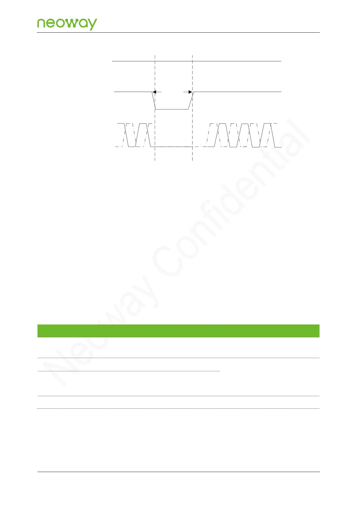
Figure 5-13 Reset process of the N715-EA module
VBAT
RESET_N
Inactive
Active
T>50ms
UART
Active
5.3 Peripheral Interfaces
N715-EA provides various peripheral interfaces.
In all reference designs of this section, the receiving and sending directions included in the pin names
of the peripheral interface of the module are based on the module, whereas peripheral pins are named
based on the components. For example, UART_TXD indicates the pin used by the module to send
data, and MCU_RXD indicates the pin used by the MCU to receive data. These two pins should be
connected.
Please note the signal naming of pins on the components in peripheral selection and design.
5.3.1 USB
USB insertion detection pin
4.5 V < USB_VBUS < 5.2 V typical
value: 5 V
USB 2.0. 90 nominal differential
characteristic impedance.
This pin is used for software
download and data transmission.
N715-EA can implement program download, data communications, and debugging through the USB
interface. The USB of N706 only supports slave mode. Figure 5-14 shows the recommended USB
interface circuit.