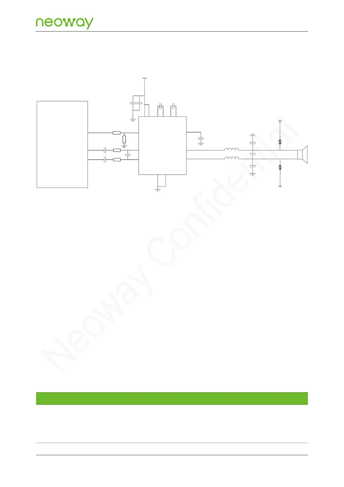
Reference Design with External Power Amplifier
Figure 5-28 Reference design of the external power amplifier connection
Schematic Design Guidelines
⚫
Connect the SPK/EAR output of the module to the power amplifier with differential connection
and select a power amplifier that can support differential input for the audio connection.
⚫
Note that the over-current capability of L1 and L2 must meet the current demand at the
maximum power. DCR is recommended to be less than 100 mΩ.
PCB Design Guidelines
⚫
Ensure that the width of audio input/output traces be no less than 0.5 mm.
⚫
The analog audio traces should be surrounded with ground and comply with the differential
routing rules. Isolate the traces from digital signals and clocks as well as other analog signal
traces. No signal trace crossing is allowed. Reserve enough grounding holes and ground
protection.
5.4.3 Headset Interface
N715-EA headset interface pinouts:
Table 5-2 Headset audio pin description