N715-EA Hardware User Guide
Chapter 5 Application Interfaces
Copyright © Neoway Technology Co., Ltd. All rights reserved.
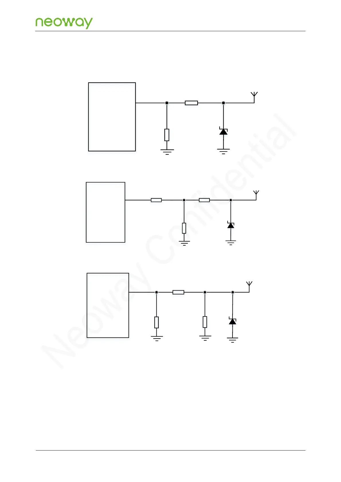
divided into three types: L type, T type, and π type. As shown in the figure below, it is recommended to
reserve a π-type matching circuit for better RF performance.
Figure 5-31 L-type network
N715-EA
Module
ANT_MAIN
Z2
D1
Z1
Figure 5-32 T-type network
N715-EA
Module
ANT_MAIN
Z2
D1
Z1
Z3
Figure 5-33 π-type network
N715-EA
Module
ANT_MAIN
Z2
D1
Z1
Schematic Design Guidelines
⚫
Element components in the above figures are capacitors, inductors, and 0 Ω resistors. Place
these RLC components as close to the antenna interface as possible.
⚫
Add an ESD protector if the antenna might generate static electricity. The protector can be a
ESD diode with a junction capacitance of less than 0.5 pF. Ensure that the reverse breakdown
voltage of the ESD greater than 10 V (above 15 V is recommended).