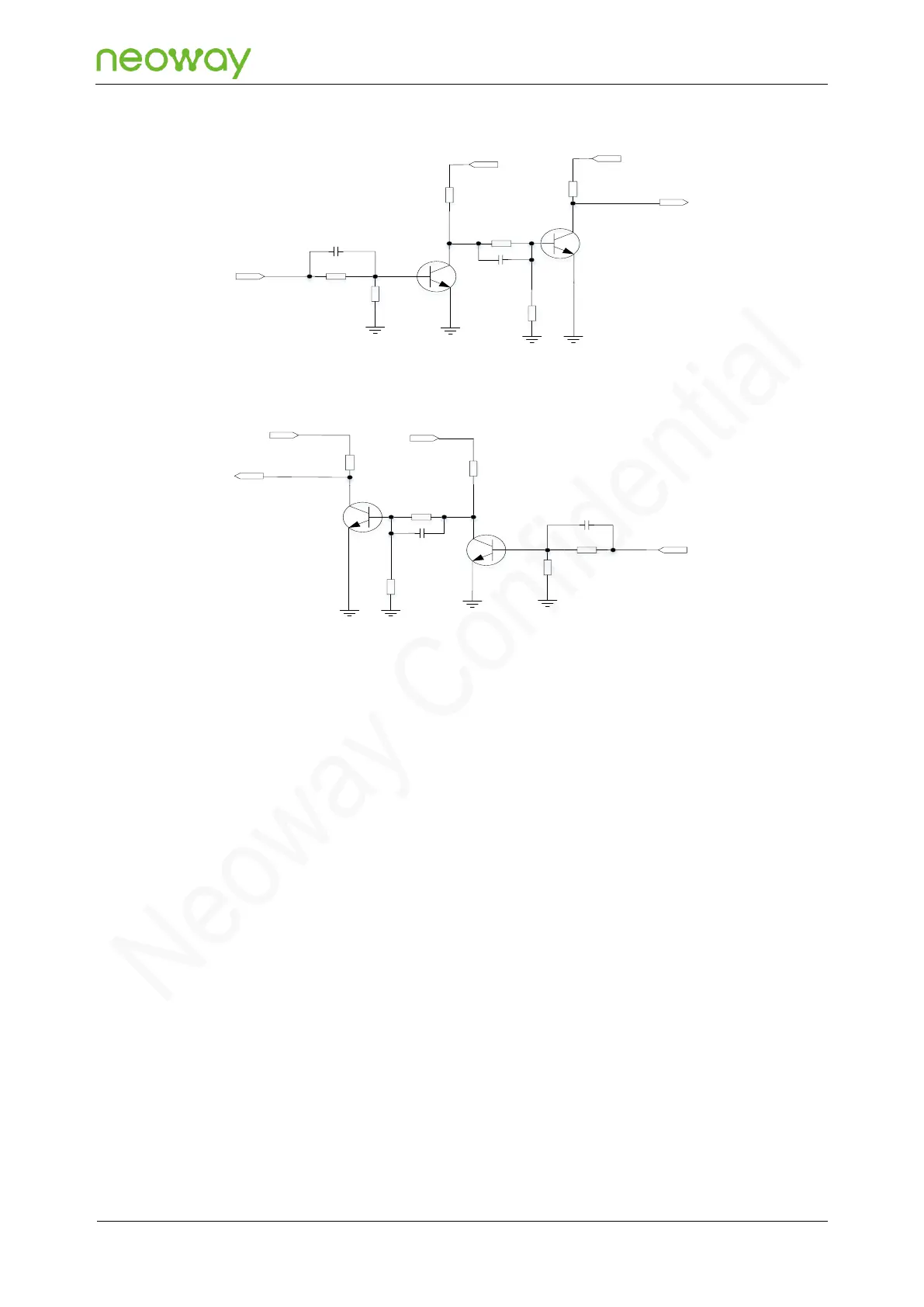
MCU_TXD and MCU_RXD are the data output and input ports of the MCU respectively, and
UART_TXD and UART_RXD are the data output and data input ports of the module respectively.
VCC_IO is the IO voltage of the MCU. VDD_1P8 is the IO voltage of the module.
The circuit translates the voltage-level through the turn-on and turn-off of the triode, and dual triode
can achieve higher pressure difference after voltage-level translation.
Schematic Design Guidelines
− Ensure that the base voltage of the triode is operating within the temperature range and the
transistor can be fully turned on.
− It is recommended to reserve the acceleration capacitor, which can adjust the delay of the
level conversion circuit in some cases.
⚫
Single-triode Voltage-Level Translation Circuit
Design the serial port pins CTS/RTS/DCD/RI by reference to recommended voltage-level
translation circuit 3, as shown in Figure 5-18.