N715-EA Hardware User Guide
Chapter 5 Application Interfaces
Copyright © Neoway Technology Co., Ltd. All rights reserved.
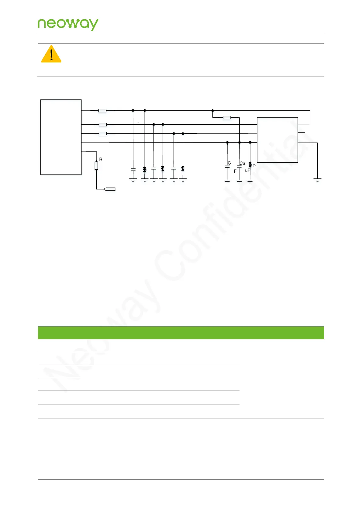
If the USIM card hot-swapping function is not used, the USIM_DET pin must be pulled up to 1.8 V with a 47 kΩ
resistor in series, and the USIM hot-swapping detection function must be disabled in software. Figure 5-21 shows
the reference design of USIM card (without hot-swapping function) interface.
Figure 5-21 Reference design of the USIM card (without hot-swap) interface
N715-EA Module
USIM_CLK
USIM_RESET
USIM_VCC
USIM_DET
CLK
RST
VCC
R2
R3
R4
20Ω
20Ω
1
.
4
5
USIM_DATA
R1 20Ω
DATA
VPP
GND
USIM Card Slot
R5
4.7kΩ
R6
47kΩ
VDD_1P8
C1
C2
C3
C6
D1
D2
D3
D5
C5
1uF
0.1uF
PCB Design Guidelines
⚫
USIM signals are like to be jammed by RF radiation, resulting in failure to detect the USIM card.
Keep USIM cards far away from the area where antennas and RF circuits are located.
⚫
Keep USIM cards close to the module and keep USIM traces as short as possible.
⚫
On the USIM traces, connect the series resistor and ESD protection component close to the
USIM card.
⚫
In order to enhance EMC, surround USIM traces with ground.
5.3.4 SDIO
Used for external WLAN
chip
The module provides one SDIO2 interface, which can be used to connect the external WLAN chip.
With the high-speed nature of the SDIO2 data signals, careful attention must be paid to PCB layout
and design to maintain adequate signal integrity.