⚫
Power-on process
To switch the module on, you can first apply a voltage at the VBAT module supply input and then force
a low pulse for greater than 2s at PWRKEY_N. The AT function is available after 5 seconds. Do NOT
connect an external resistor with large resistance in series to the PWRKEY_N pin (a 470 Ω resistor is
recommended) since there is already an internal 1 kΩ series resistor. Otherwise, the module cannot
be switched on since the PWRKEY_N is at a high level all the time.
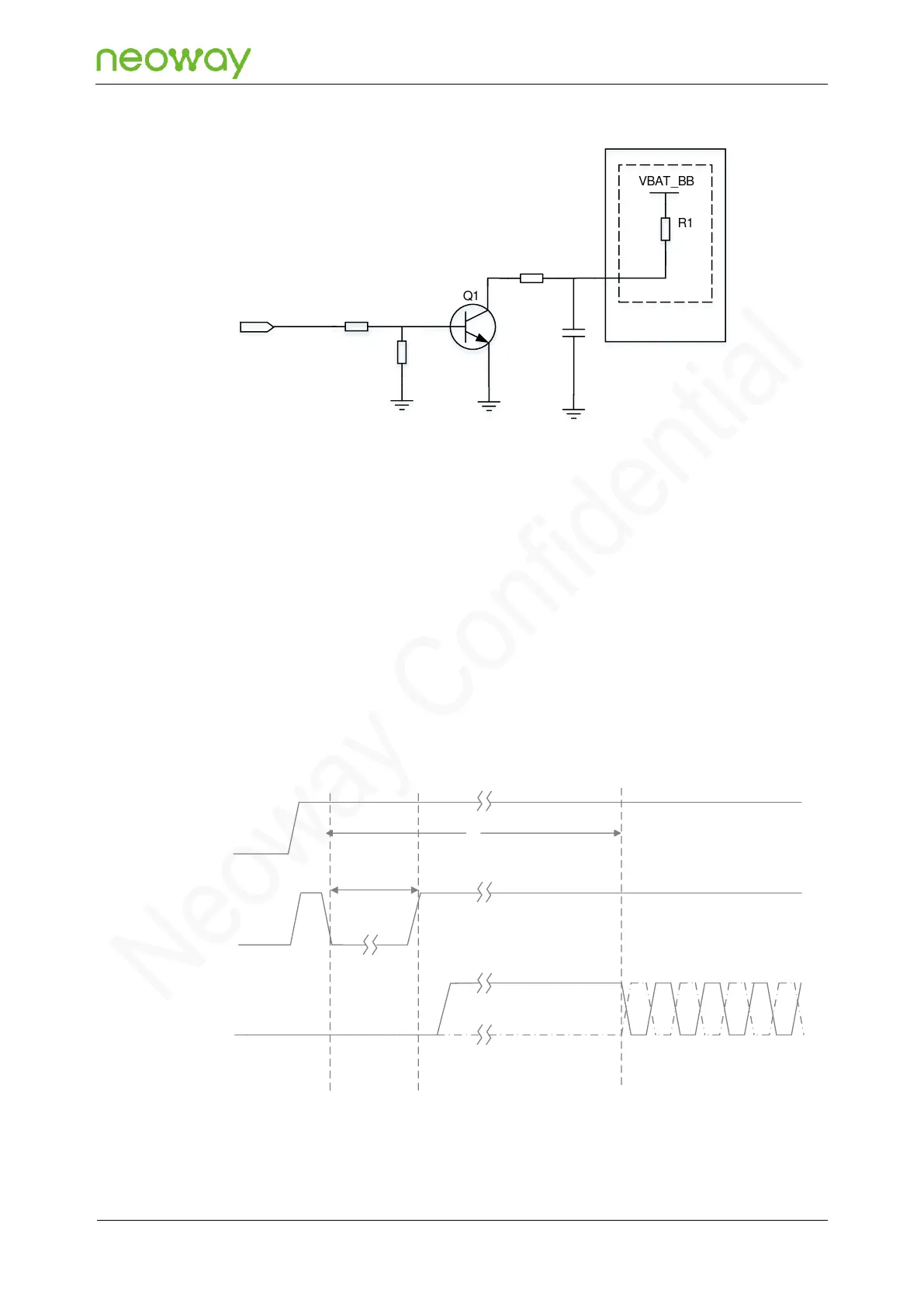
After the module is switched on, it needs to perform initialization process untill the pin state is stable,
and during the process, do not perform other operations on the module. The following figure shows the
power-on process:
Figure 5-8 Power-on process