N715-EA Hardware User Guide
Chapter 5 Application Interfaces
Copyright © Neoway Technology Co., Ltd. All rights reserved.
Registered network
mode indication
Note: If the USIM2 interface is not used, pins
#52 to #54 are available; otherwise, leave
these pins open. If status indication is
required, it should be multiplexed from the
other not pin that is not used; for more details,
contact Neoway.
Network status
indication
Note: If the USIM2 interface is not used, pins #52 to #54 are available; otherwise, leave these pins open. If status
indication is required, it should be multiplexed from the other not pin that is not used; for more details, contact
Neoway
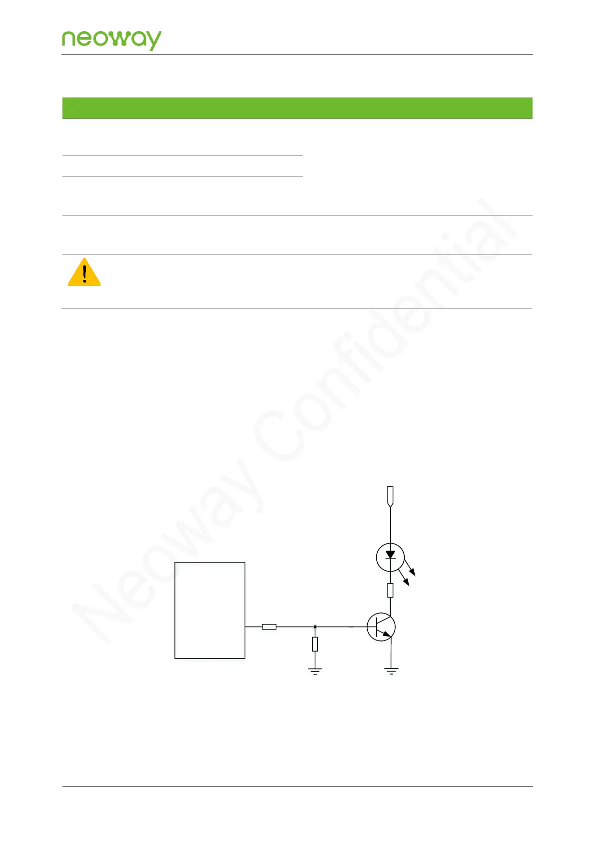
NET_MODE, SLEEP_IND, and NET_LIGHT are respectively the registered network mode indication,
sleep mode indication, and network status indication pins. They output PMW waves of duty cycle
varying with the status of the module and drives an LED indicator to blink at different frequencies. You
can use the AT+SIGNAL command to enable the LED indicator to blink in different states. For detailed
usage, see Neoway_N715-EA_AT_Commands_Manual.
Do not use the indication pin to drive the LED indicator directly since the pin outputs a high level of 1.8
V. It is recommended to drive the LED indicator by controlling a triode.
Figure 5-43 Driving LED indicator with a triode
R2
N715-EA
Module
NET_LIGHT
R1 4.7kΩ
VCC
47kΩ
Q1
D1
1kΩ
R3