EasyManua.ls Logo

Neoway N715-EA - USIM Interface Overview

Default Icon
86 pages
Print Icon
To Next Page IconTo Next Page
To Previous Page IconTo Previous Page
Loading...
N715-EA Hardware User Guide
Chapter 5 Application Interfaces
Copyright © Neoway Technology Co., Ltd. All rights reserved.
44
Figure 5-18 Recommended voltage-level translation circuit 3
MCU_CTS
UART_RTS
R3
10kΩ
R2
4.7kΩ
VCC_IO
VDD_1P8
Q1
UART_CTS
MCU_RTS
R1
10kΩ
R4
4.7kΩ
VDD_1P8
Q2
C1
10pF
C2
10pF
C3
10pF
C4
10pF
MCU_CTS and MCU_RTS are the MCU-side signals; UART_CTS and UART_RTS are the module-
side signals. VCC_IO is the IO voltage of the MCU. VDD_1P8 is the IO voltage of the module.
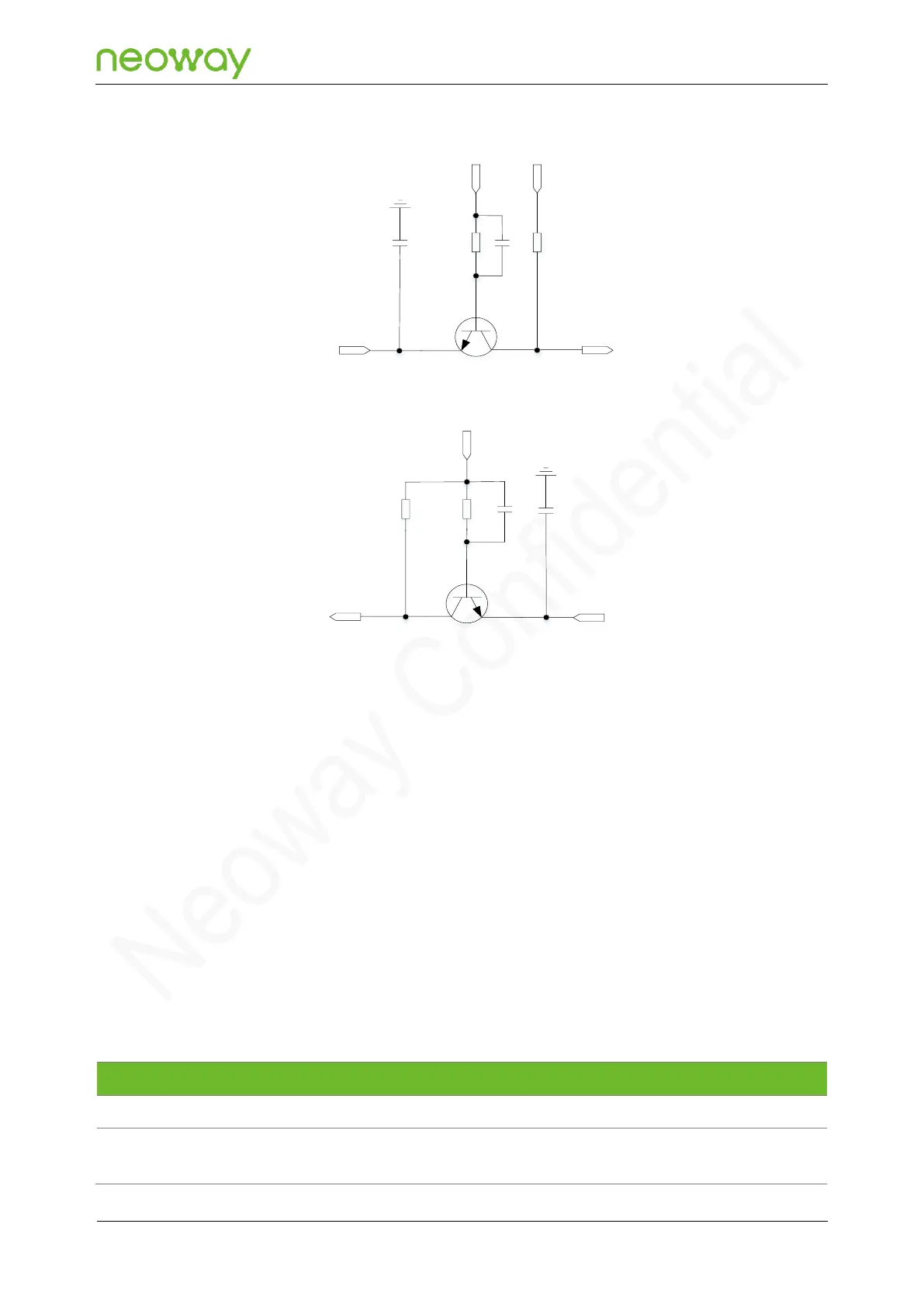
The circuit translates the voltage-level through the turn-on and turn-off of the triode, and the translation
is unidirectional. Pay attention to the signal flow.
Schematic Design Guidelines
Ensure that the voltage difference between the high-level and low-level sides is not greater
than 2 V.
For the accelerating capacitor, adjust it according to the actual test conditions; it is
recommended to reserve the capacitor.
The base voltage of the transistor is the lower voltage between both sides.
5.3.3 USIM
Signal
Pin
I/O
Function description
Remarks
USIM1_VCC
8
PO
USIM1 power output
1.8 V/3.0 V (self-adaptive)
USIM1_DATA
6
B
USIM1 data input and
output
Connecting this pin to
USIM1_VCC through a 4.7

Table of Contents