293
GS748T Smart Switch
VLAN Routing
VLANs divide a single physical network (broadcast domain) into separate logical networks.
To forward traffic across VLAN boundaries, a layer 3 device, such as router, is required. The
GS748T Smart Switch can act as a layer 3 device when you configure VLAN routing
interfaces. VLAN routing interfaces make it possible to transmit traffic between VLANs while
still containing broadcast traffic within VLAN boundaries. The configuration of VLAN routing
interfaces makes inter-VLAN routing possible.
For each VLAN routing interface, you can assign a st
atic IP address, or you can allow a
network DHCP server to assign a dynamic IP address.
When a port is enabled for bridging (L2 switching) ra
ther than routing, all normal bridge
processing is performed for an inbound packet, which is then associated with a VLAN. Its
MAC Destination Address (MAC DA) and VLAN ID are used to search the MAC address
table. If routing is enabled for the VLAN, and the MAC DA of an inbound unicast packet is
that of the internal router interface, the packet is routed. An inbound multicast packet is
forwarded to all ports in the VLAN, plus the internal bridge-router interface, if it was received
on a routed VLAN.
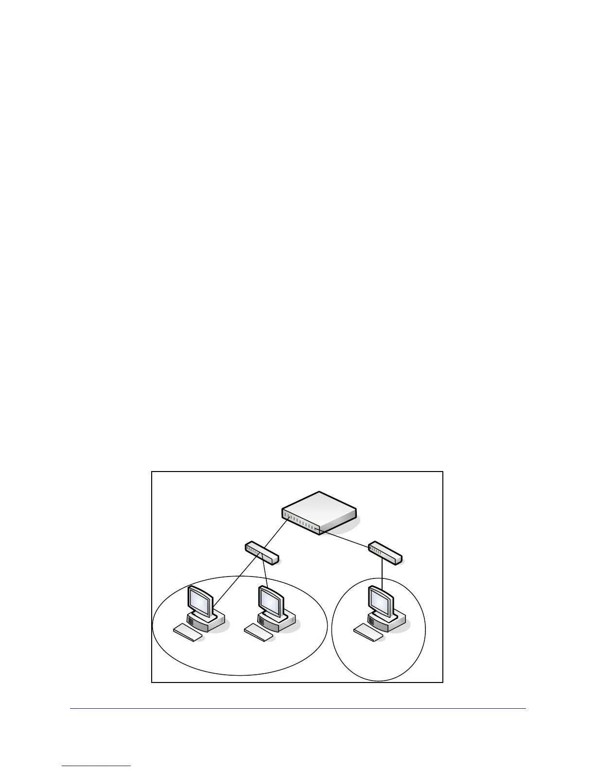
VLAN Routing Configuration Example
This section provides an example of how to configure GS748T software to support VLAN
routing.
In the following diagram, the GS748
Tswitch is configured as an L3 device and performs the
routing functions for hosts connected to the L2 switches. For Host A to communicate with
Host B, no routing is necessary. These hosts are in the same VLAN. However, for Host A in
VLAN 10 to communicate with Host C in VLAN 20, the GS748T switch must perform
inter-VLAN routing.
` ` `
L3 Switch (GS748T)
L2 Switch
L2 Switch
Host A
Host B
Host C
VLAN 10
VLAN 20
Port g3
Port g20
 Loading...