Do you have a question about the NETGEAR GS752TP and is the answer not in the manual?
The NETGEAR switch contains an embedded web server and management software for managing and monitoring switch functions.
To enable remote management of the switch through a web browser or SNMP, you must connect the switch to the network and configure it with network information.
This section describes how to set up your switch in a network that has a DHCP server.
To access the switch management interface, use one of the following methods.
This section describes how to display the switch status and specify some basic switch information, such as the management interface IP address, system clock settings, and DNS information.
Use the IP Configuration screen to configure network information for the management interface, which is the logical interface used for in-band connectivity with the switch.
The Green Ethernet features allow the switch to reduce power consumption on a per-port basis.
The screens you access from the Ports menu allow you to view and monitor the physical port information for the ports available on the switch.
Adding virtual LAN (VLAN) support to a Layer 2 switch offers benefits of both bridging and routing.
Spanning Tree Protocol (STP) provides a tree topology for any arrangement of bridges and helps eliminate loops.
Use the IP Configuration screen to configure routing parameters for the switch.
You can configure the switch software with some ports supporting VLANs and some supporting routing.
The Address Resolution Protocol (ARP) associates a Layer 2 MAC address with a Layer 3 IPv4 address.
The Class of Service (CoS) queueing feature lets you directly configure certain aspects of switch queueing.
The QoS feature provides Differentiated Services (DiffServ) support that enables traffic to be classified into streams.
From the Management Security menu, you can configure the login password, RADIUS settings, TACACS+ settings, and authentication lists.
In port-based authentication mode, when 802.1x is enabled globally and on the port, successful authentication of any one supplicant attached to the port results in all users being able to use the port without restrictions.
Access control lists (ACLs) ensure that only authorized users have access to specific resources while blocking off any unwarranted attempts to reach network resources.
The screens available from the Ports menu contain various information about the number and type of traffic transmitted from and received on the switch.
The switch might generate messages in response to faults, or errors occurring on the platform as well as changes in configuration or other occurrences.
The Troubleshooting menu contains links that provide access to the features described in the following sections: Ping, Ping IPv6, Traceroute, Remote Diagnostics.
The Reset menu contains links that provide access to the features described in the following sections: Device Reboot, Factory Default.
The switch supports system file uploads from the switch to a remote system by using either TFTP or HTTP.
The Troubleshooting menu contains links that provide access to the features described in the following sections: Ping, Ping IPv6, Traceroute, Remote Diagnostics.
The Online Help link provides links to the sections described in the following sections: Support, User Guide.
Use the Registration screen to register your switch. Completing the registration confirms your email address, lowers technical support resolution time.
This section lists the features supported by the switch and their default configurations.
A virtual LAN (VLAN) is a local area network with a definition that maps workstations on some basis other than geographic location.
ACLs ensure that only authorized users have access to specific resources while blocking off any unwarranted attempts to reach network resources.
Port-based network access control makes use of the physical characteristics of LAN infrastructures to provide a means of authenticating and authorizing devices attached to a LAN port.
Spanning Tree Protocol (STP) runs on bridged networks to help eliminate loops. MSTP supports multiple instances of spanning tree.
VLANs divide broadcast domains in a LAN environment. Inter-VLAN routing is accomplished by creating Layer 3 interfaces.
| Switch type | Managed |
|---|---|
| Switch layer | L3 |
| Quality of Service (QoS) support | Yes |
| Number of multicast groups filtered | 1024 |
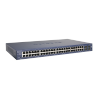
| Fiber optic connector | SFP |
| SFP module slots quantity | 4 |
| Basic switching RJ-45 Ethernet ports type | Gigabit Ethernet (10/100/1000) |
| Basic switching RJ-45 Ethernet ports quantity | 48 |
| 10G support | - |
| Number of VLANs | 256 |
| Networking standards | IEEE 802.1D, IEEE 802.1s, IEEE 802.1w, IEEE 802.1x, IEEE 802.3af, IEEE 802.3at, IEEE 802.3x |
| Copper ethernet cabling technology | 1000BASE-T, 100BASE-T, 10BASE-T |
| DHCP features | DHCP client |
| MAC address table | 8000 entries |
| Packet buffer memory | 8 MB |
| Number of static routes | 32 |
| Supported network protocols | IPv4, IPv6, TFTP, SNTP, TACACS+ |
| Power consumption (typical) | 384 W |
| Safety | CE, CSA, UL |
| Product color | Gray |
| Electromagnetic compatibility | CE, FCC, Class A EN 55022, Class A C-Tick, EN 50082-1, EN 55024, CCC |
| Mean time between failures (MTBF) | 220447 h |
| Heat dissipation | 1750.70 BTU/h |
| Operating altitude | 0 - 3000 m |
| Storage temperature (T-T) | -20 - 70 °C |
| Operating temperature (T-T) | 0 - 55 °C |
| Storage relative humidity (H-H) | 0 - 95 % |
| Operating relative humidity (H-H) | 10 - 90 % |
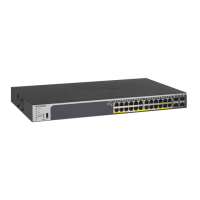
| Total Power over Ethernet (PoE) budget | 15.4 W |
| Power over Ethernet plus (PoE+) ports quantity | 8 |
| Cables included | AC |
| Depth | 316 mm |
|---|---|
| Width | 440 mm |
| Height | 43 mm |
| Weight | 5100 g |