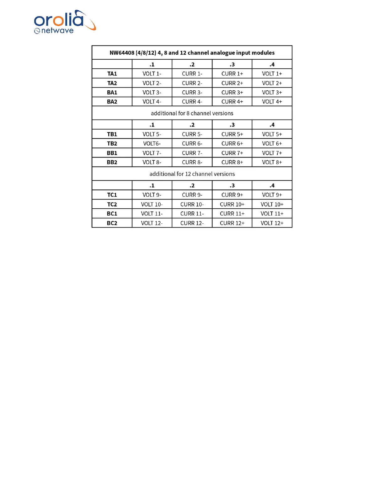
Figure 18.4.4 – Connection table Analogue Modules
18.5 Data communications
These adaptors send analogue data (-10V to +10V or -20mA to -20mA) they receive from their
input ports onto the busbar ‘backplane’ for further processing by the Buscoupler which in its turn
streams the data onto the (VDR) network.
18.6 Indicators
All adaptors have the number of ‘channel LEDs’ (CH1~24) corresponding with their size (8,16,24)
and each row of 8 channels has a LINK led which indicates if that part of the adaptor has power
and has established a data-link with the Buscoupler.
18.7 Errors
If errors occur within the adaptor these will be indicated on the display of the Bridge Display Unit.
18.8 Configuration
The input is auto-sensing, and the unit does not require any manual configuration (other than to
set the recording channel name associated with the physical connection during the commissioning
process).
18.9 Operating instructions
After commissioning of the VDR system, this unit does not require (crew) operating instructions.