16.5 Data communications
The adaptor sends its data to the NW6410 Buscoupler for further processing and streaming onto
the VDR network. In default ‘VDR mode’ in order to offload its data – the Buscoupler relies on the
ethernet connection to the Core Module.
16.6 Indicators
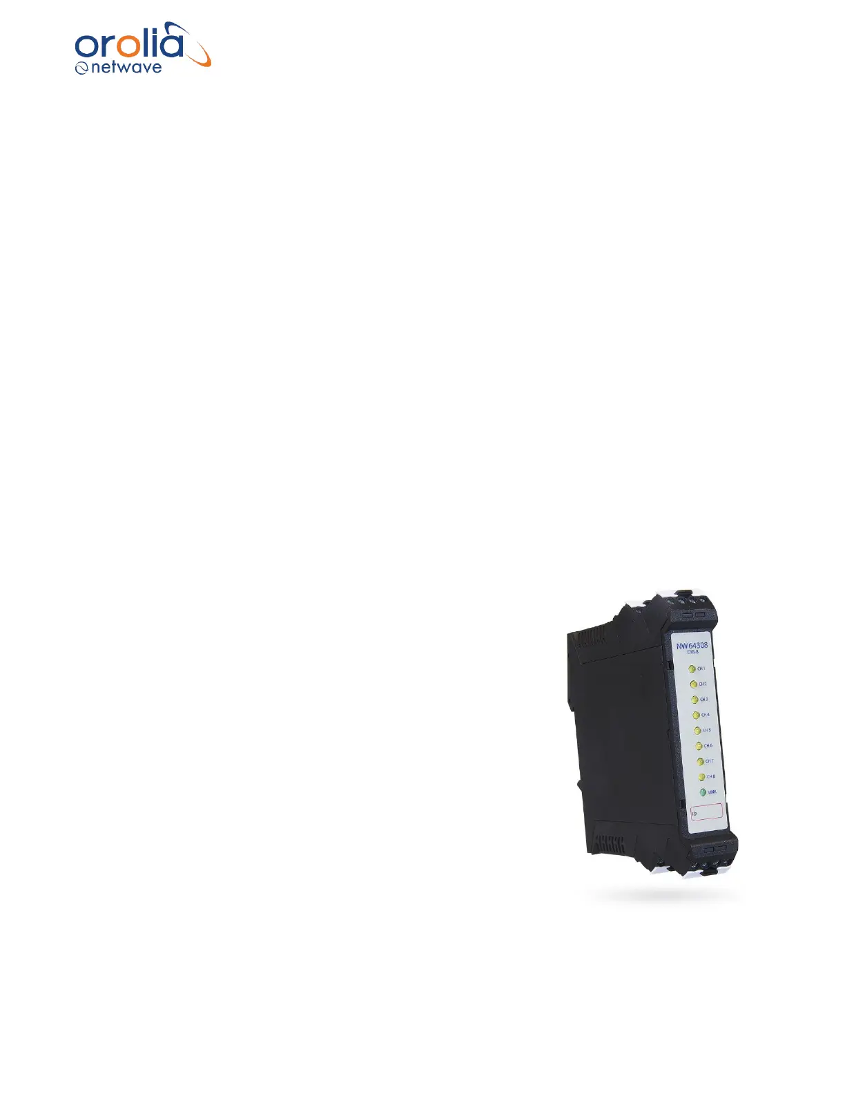
All adaptors have the number of ‘channel LEDs’ (CH1~24) corresponding with their size (8,16,24)
and each row of 8 channels has a LINK led which indicates if that part of the adaptor has power
and has established a data-link with the Buscoupler.
16.7 Errors
If errors occur within the adaptor these will be indicated on the display of the Bridge Control Unit.
16.8 Configuration
The baud-rate is auto-sensing, and the unit does not require any manual configuration (other than
to set the recording channel name associated with the physical connection during the
commissioning process).
16.9 Operating instructions
After commissioning of the VDR system, this unit does not require (crew) operating instructions.
17. NW64308/16/24 Digital 8/16/24 channel adaptors
17.1 General
ON level 5-24V DC, max. input current 1mA. The modules are
available in 8,16 and 24 channel configurations within a
harmonized configuration and wiring scheme.
These adaptors send digital data they receive from their input ports
onto the busbar ‘backplane’ for further processing by the
Buscoupler which in its turn streams the data onto the (VDR)
network.
17.2 Mounting
These adaptors connect to the DIN busbar within the DAQ
enclosure by mounting them from the top first and only in a vertical
direction. Once the adaptor is attached to the DIN rail it should not
be shifted in a horizontal direction (!) since this will render the
feathering contacts between the adaptor and the DIN useless and
the system will fail beyond repair.