NMC-WOLLARD 2021Truax Blvd., Eau Claire, WI 54703, Phone (715) 835-3151, Fax (715) 835-6625
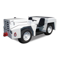
M140 Tow Tractor Manual No. 46054
PAGE 3-1
CHAPTER 2 MAINTENANCE
3 REMOVAL AND INSTALLATION
AUGUST 31, 2008
3. REMOVAL AND INSTALLATION
Perform lockout/tagout procedures before adjusting, lubricating,
cleaning or otherwise servicing. Failure to do so could result in unexpected startup
and could cause serious injury or death.
3.1 AXLE
1. Remove rear wheels.
2. Drain axle lubricant according to steps 3-7.
3. Remove pipe clamps holding exhaust pipe and tail pipe to frame.
Disconnect exhaust pipe at exhaust manifold and remove exhaust system.
4.
and swing drive shaft out of the way. Tape bearing to universal joint spider
to prevent losing bearings.
5. Disconnect brake lines from wheel cylinders and remove hardware
contamination. Move brake lines and secure to frame to prevent damage
to lines.
6.
7. Position an axle jack or other mobile lifting device under axle and raise it
enough to relieve tension. Remove capscrews to free axle unit from tractor
and lower axle.
8. Raise tractor until rear axle unit can be moved from under tractor.
9.
obtained at the rear, slide unit outside of tractor.
NOTICE! Do not attempt to clean assembled units using steam or by dipping
in solvent. These methods will result in premature axle failure. Complete
disassembly is necessary for thorough cleaning.
3.1.1 Disassembly of Rockwell Dierential and Drive Pinion
perform steps 4-12 only.
1. Remove axle according to 3.1.
4. Turn axle so cover side is up.
5. Remove the six (6) from pinion cage assembly.