NMC-WOLLARD 2021Truax Blvd., Eau Claire, WI 54703, Phone (715) 835-3151, Fax (715) 835-6625
M140 Tow Tractor Manual No. 46054
PAGE 3-23
CHAPTER 2 MAINTENANCE
IMPORTANT: There is a RH and LH brake hose. Place a hose block over
the port in the brake caliper. If the steel hose ell from the hose block angle
upward and back it is for this side. If it does not, this hose is for the opposite
side.
8. Bleed the front brakes as instructed in 2-1 -1.10.
9. Install front wheels and tighten mounting nuts to 120 ft-lbs torque.
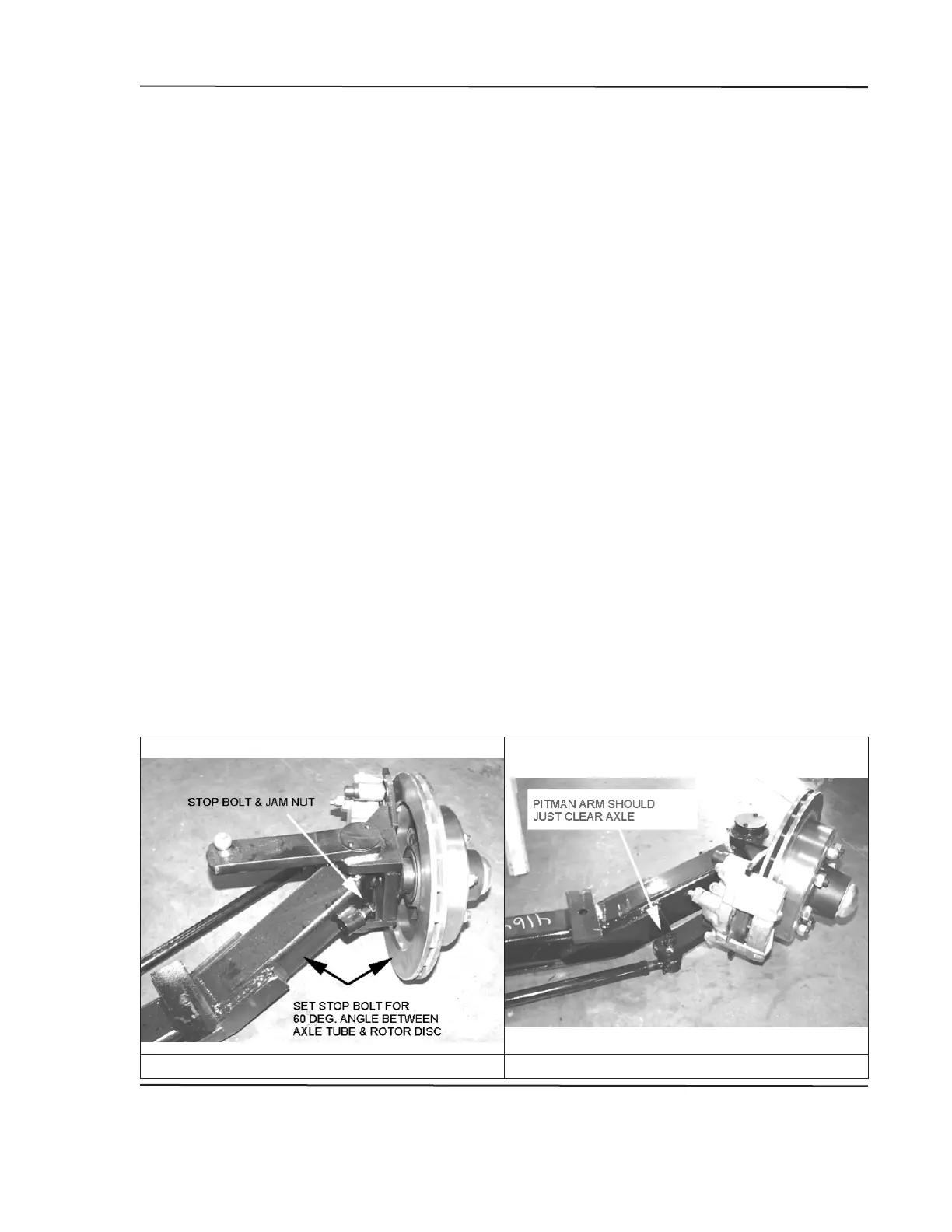
3.13.5 Setting Stops On New Axle
1. There must be weight on the axle when making this adjustment, so leave
the machine on the ground. Alternately, the unit can be raised back up
onto the and then use the axle jack to raise up on the axle until the it
relieves slack from the springs. This procedure will make it easier to work
on the machine to make the remaining adjustments.
2. The axle stops maybe preset by the manufacturer, but need to be
checked.
3. The included angle between the axle tube and the brake rotor disk is 60
4. If adjustment is required, turn the hub until you measure a 60 degree
angle with an adjustable protractor or template. Move the stop bolt out
until it contacts the axle pivot weldment.
5. When adjustment is correct, lock stop bolt with jam nut.
NOTE: If stop bolt supplied with axle is not long enough to make adjustment,
replace it with a 1/2-13x2.50 hex bolt.
AUGUST 31, 2008
3 REMOVAL AND INSTALLATION
FIGURE 3. SETTING AXLE STOPS FIGURE 4. STEERING ARM