NMC-WOLLARD 2021Truax Blvd., Eau Claire, WI 54703, Phone (715) 835-3151, Fax (715) 835-6625
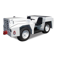
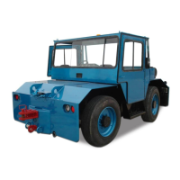
M140 Tow Tractor Manual No. 46054
PAGE 5-89
CHAPTER 5 MANUFACTURER’S INFORMATION
ii
List of Figures
Figure 1-1: Menu Scrolling and Option Selection � � � � � � � � � � � � � � � � � � � � � � � � � � � � � � � � 2
Figure 1-2: Blinking Bar Cursor � � � � � � � � � � � � � � � � � � � � � � � � � � � � � � � � � � � � � � � � � � � � � � � � � 3
Figure 1-3: Accessing the Main Menu � � � � � � � � � � � � � � � � � � � � � � � � � � � � � � � � � � � � � � � � � � � 4
Figure 1-4: Accessing and Resetting Maintenance Hours and Vehicle Trip Logs � � � 5
Figure 1-5: Fault Notication and Information Screens � � � � � � � � � � � � � � � � � � � � � � � � � � � 6
Figure 1-6: Viewing Active Faults � � � � � � � � � � � � � � � � � � � � � � � �
� � � � � � � � � � � � � � � � � � � � � � � 7
Figure 1-7: Warning Notication and Information Screens � � � � � � � � � � � � � � � � � � � � � � � 8
Figure 1-8: Viewing Active Warnings � � � � � � � � � � � � � � � � � � � � � � � � � � � � � � � � � � � � � � � � � � � � 9
Figure 1-9: Faults Stored Information Screens � � � � � � � � � � � � � � � � � � � � � � � � � � � � � � � � � � 10
Figure 1-10: Alarms Menu Functions � � � � � � � � � � � � � � � � � � � � � � � � � � � � � � � � � � � � � � � � � � � 12
Figure 1-11: Enabling/Disabling Alarms � � � � � � � � � � � � �
� � � � � � � � � � � � � � � � � � � � � � � � � � � 13
Figure 1-12: Alarm Screen Details � � � � � � � � � � � � � � � � � � � � � � � � � � � � � � � � � � � � � � � � � � � � � � 14
Figure 1-13: Viewing Alarms � � � � � � � � � � � � � � � � � � � � � � � � � � � � � � � � � � � � � � � � � � � � � � � � � � � 14
Figure 1-14: Add & Edit Alarm CAN Parameter Screen Details � � � � � � � � � � � � � � � � � � � 15
Figure 1-15: Menu Prompt Sequence with No Congured Alarms � � � � � � � � � � � � � � � 16
Figure 1-16: Menu Prompt Sequence with Previously Congured Alarms � � � � � � � 17
Figure 1-17: Editing an Alarm � � � � � � � � � � �
� � � � � � � � � � � � � � � � � � � � � � � � � � � � � � � � � � � � � � � 18
Figure 1-18: Deleting an Alarm � � � � � � � � � � � � � � � � � � � � � � � � � � � � � � � � � � � � � � � � � � � � � � � � 19
Figure 1-19: Muting Faults, Warnings & Alarms � � � � � � � � � � � � � � � � � � � � � � � � � � � � � � � � � 20
Figure 1-20: Setup Menu Functions � � � � � � � � � � � � � � � � � � � � � � � � � � � � � � � � � � � � � � � � � � � � 21
Figure 1-21: Setting Backlight Intensity � � � � � � � � � � � � � � � � � � � �
� � � � � � � � � � � � � � � � � � � � 22
Figure 1-22: Setting Units � � � � � � � � � � � � � � � � � � � � � � � � � � � � � � � � � � � � � � � � � � � � � � � � � � � � � 23
Figure 1-23: Popup Fault, Warning & Alarm Screens � � � � � � � � � � � � � � � � � � � � � � � � � � � � 24
Figure 1-24: Setting Popup Status � � � � � � � � � � � � � � � � � � � � � � � � � � � � � � � � � � � � � � � � � � � � � 25
Figure 1-25: Display Menu � � � � � � � � � � � � � � � � � � � � � � � � � � � � � � � � � � � � � �
� � � � � � � � � � � � � � � 26
Figure 1-26: 1 and 2 CAN Parameter Display Formats � � � � � � � � � � � � � � � � � � � � � � � � � � � 27
Figure 1-27: Setting 1 or 2 Parameter Display Lines � � � � � � � � � � � � � � � � � � � � � � � � � � � � � 27
Figure 1-28: Setting LCD Contrast � � � � � � � � � � � � � � � � � � � � � � � � � � � � � � � � � � � � � � � � � � � � � � 28
Figure 1-29: Video Mode Formats � � � � � � � � � � � � � � � � � � � � � � � � � � � � � � � � � � � � � � � � � � � � � � 29
Figure 1-30: Setting LCD Background Color Scheme (Video Mode) � � � � � � � � � � � � � � 30
Figure 1-31: S
etting Hours or Miles for Main Menu Display � � � � � � � � � � � � � � � � � � � � � 31
Figure 1-32: Setting Alarm Output Pin Status � � � � � � � � � � � � � � � � � � � � � � � � � � � � � � � � � � � 32
Figure 1-33: Viewing Firmware Revision � � � � � � � � � � � � � � � � � � � � � � � � � � � � � � � � � � � � � � � � 33
NexSysLink
®
2" Stand-Alone CAN Display Operation Manual SAE J1939
CAN DISPLAY MANUAL
OCTOBER 01, 2015