NMC-WOLLARD 2021Truax Blvd., Eau Claire, WI 54703, Phone (715) 835-3151, Fax (715) 835-6625
M140 Tow Tractor Manual No. 46054
PAGE 1-37
CHAPTER 2 MAINTENANCE
AUGUST 31, 2008
1 SERVICING
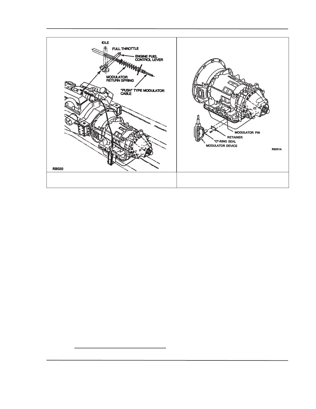
FIGURE 12. MECHANICAL MODULATOR
INSTALLATION
FIGURE 13. MECHANICAL
MODULATOR COMPONENTS
Design requirements for a mechanical modulator are shown on separate Shift
Modulator Installation Drawings for each transmission series. The mounting
location of the modulator is shown on both the Shift Modulator and Basic
Installation Drawing for each transmission.
The system design should provide for ease of installation and adjustment.
Adjust at full throttle position to insure maximum speed upshifts at full throttle.
The modulator must provide a force against the transmission modulator pin,
in proportion to cable travel, as described on the appropriate Shift Modulator
“push” or “pull” cable motion when the fuel lever moves from closed to full
throttle position.
Figure 12 illustrates a recommended type of connection of the end of a “push
type” modulator cable to the engine fuel lever. This type of arrangement will
allow the fuel lever to return to idle even if the actuator binds somewhere in
its travel between idle and full throttle positions. With this system, a return
spring is required on the actuator linkage to insure that the actuator follows
the movement of the fuel lever (throttle). The spring should be designed for
the particular installation and have a low spring rate to keep the additional
accelerator pedal force as low as possible. For suppliers of the mechanical
modulator, refer to the Support Equipment section of the appropriate
Transmission Installation Manual.