2. Connect a DC power supply to the module test jig with a power cable.
Note: Turn off the DC power supply at this stage.
3. Set the DC supply voltage to 4.2 V.
4. Set the jumper connector on the test jig to the bypass position.
5. Set the phone mode switch to LOCAL position.
6. Place the phone module to the test jig.
7. Turn on the DC power supply, and wait for the LED jig to turn on.
8. Start Phoenix service software on your PC.
Note: Make sure that the Phoenix service software version on your computer is not older than
version of week 8 of 2008.
9. Initialize Phoenix connection to the phone.
10. Choose File→Scan Product .
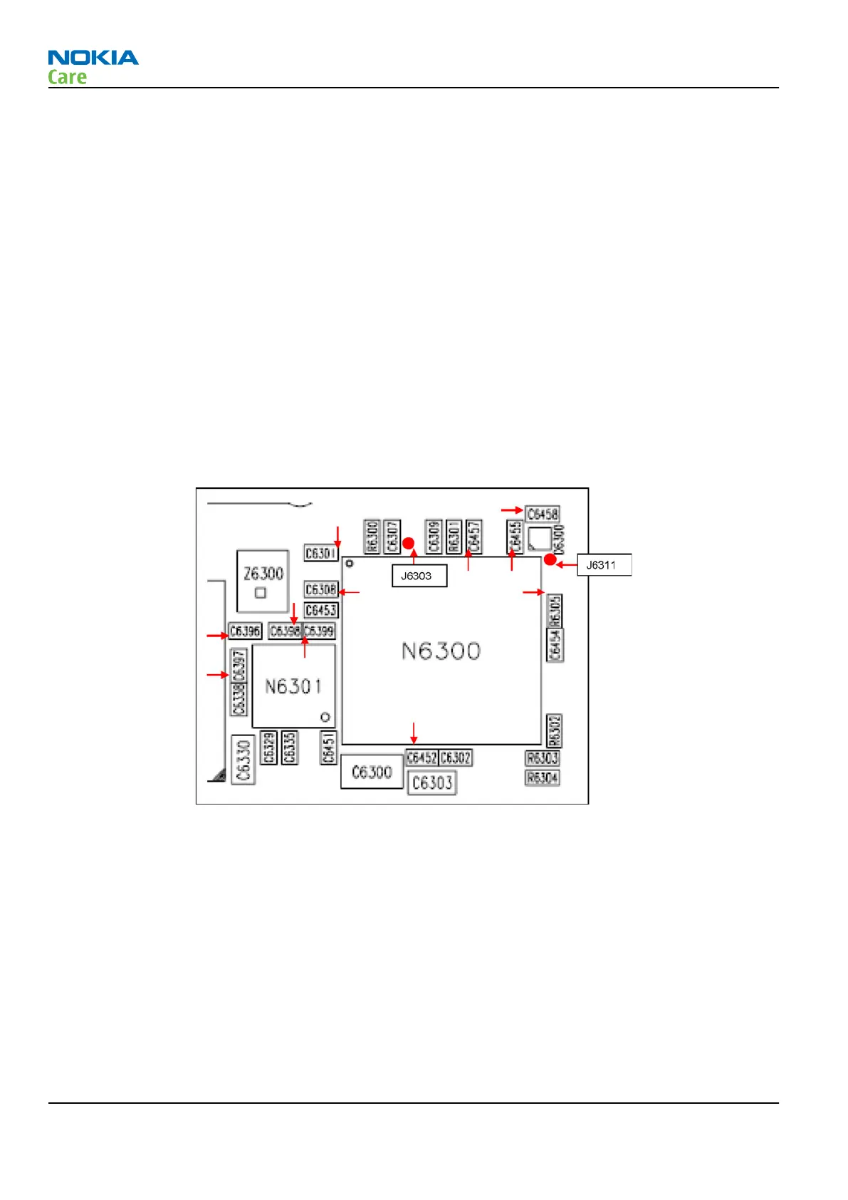
11. Once the Phoenix identifies the phone’s product information, referring to the following figure of test
points, follow the WLAN ASIC troubleshooting procedure as shown in the flowchart below. The red
arrows shown in the figures below are pointing to the test points mentioned in the troubleshooting
flowchart. Measure the voltage and frequency with a 10:1 high impedance scope probe.
Figure 37 Test points around the WLAN ASIC
RM-247
RF troubleshooting
Page 4 –26 COMPANY CONFIDENTIAL Issue 1
Copyright © 2008 Nokia. All rights reserved.
 Loading...