Table 18 Pin configuration
3.5mm Signal name Direction Description
Pin #
6 PLUGDET In Terminal internal connection, plug
detection
5 HS EAR L In / Out Audio output
4 HS EAR R In / Out Audio output,
3 HS MIC In / Out Multiplexed microphone audio and
control data, C-video out
1, 2 HS GND - Ground contacts
There are three different use cases for AV connection. In all cases the PLUG_DET is used for detecting plug
insertion and removal. EAR lines are used for FM antenna reception.
• Headset or similar with ECI or without ECI.
When a headset is detected the terminal will check if there is ECI circuit in the accessory. If the ECI chip is
present, tuning values for that is taken into use otherwise basic audio tuning parameters are used.
• Headphones
For the headphones and any 3-pole connector devices, the headphones option is used.
Note: The mic line and the ground line are connected together.
• Video out
For example, when connecting terminal to television all pins are used.
Note: The microphone is multiplexed to C-video. The cable has to be inserted first to television set
and then to the terminal, otherwise the automatic detection does not work according to the
specification.
User interface
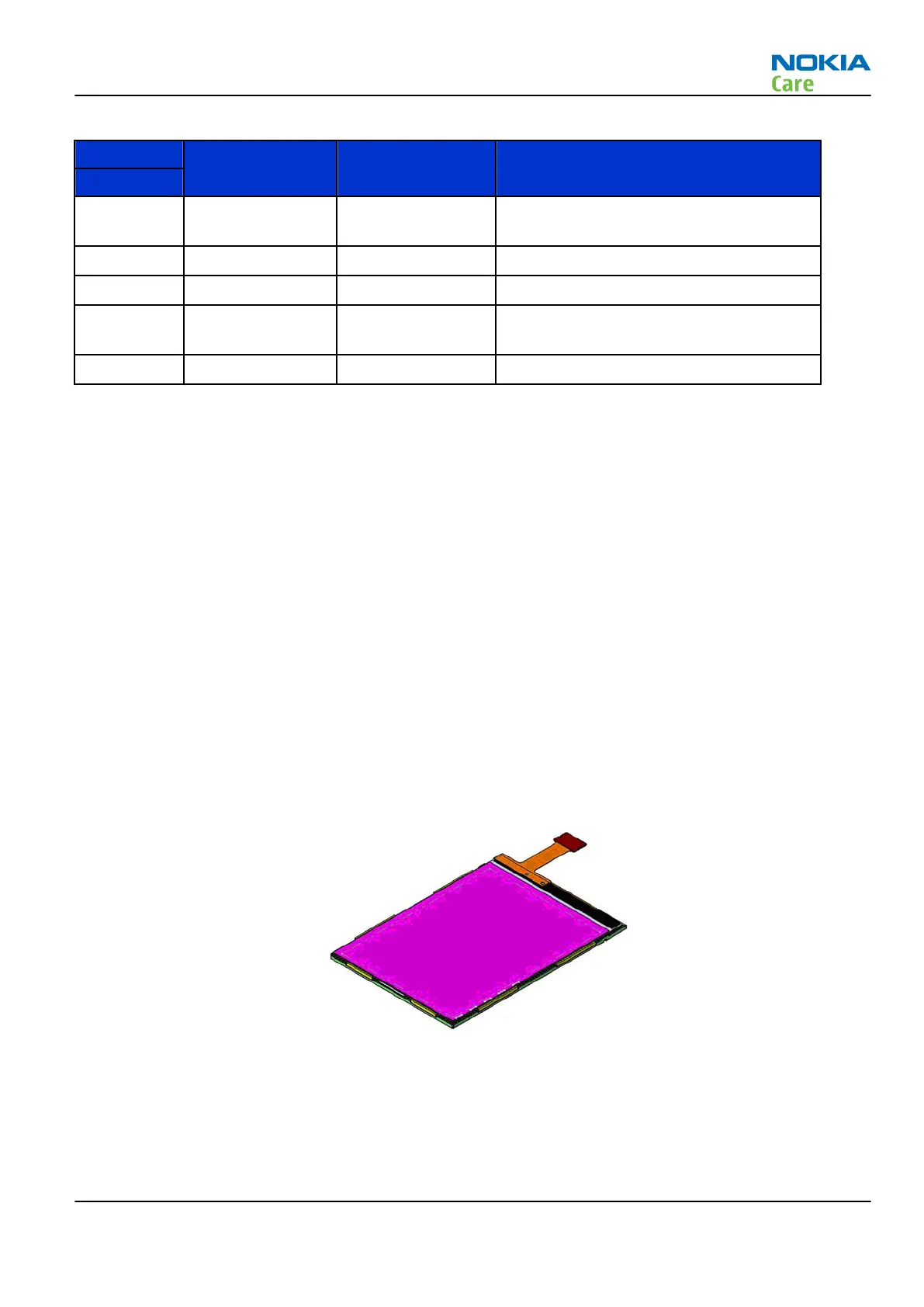
Display
Display features
• Module size (width x height x thickness) 47.48 mm X 67.14 mm X 2.041 mm
• Resolution QVGA (240*320)
• Numbers of colours up to 16.7M
• Partial display function; power saving by pausing display process on part of the screen
RM-247
System Module
Issue 1 COMPANY CONFIDENTIAL Page 7 –29
Copyright © 2008 Nokia. All rights reserved.

 Loading...